Method for reducing fuel consumption in aircraft

a fuel consumption and aircraft technology, applied in sustainable transportation, climate sustainability, transportation and packaging, etc., can solve the problems of lack of practical mechanical design, reliability and functional hardware, use of these devices for aerodynamic, structural and economic considerations, and no claims regarding fuel efficiency in aircraft, so as to reduce emissions, reduce fuel consumption, and increase the effect of climbing ra

Inactive Publication Date: 2003-07-29
AEROTECH SERVICES +1
View PDF13 Cites 54 Cited by
  • Summary
  • Abstract
  • Description
  • Claims
  • Application Information

AI Technical Summary

Problems solved by technology

Lack of practical mechanical designs, reliability, and functional hardware; restricts the use of these devices for aerodynamic, structural, and economic considerations.
While in theory this apparatus may improve lift or drag characteristics of an airfoil, the authors have made no claims regarding fuel efficiency in an aircraft.
Altering surface contours may have undesirable aerodynamic effects and loads on aircraft mechanisms controlling the flap segments.
Replacement of conventional flight control surfaces with re-contoured flight control surfaces has not been accepted or proven in the aerospace community.
It should be noted that the above two modifications to the Boeing 727 aircraft result in limiting trailing edge flap extension.
The aforementioned prior art, some of which is theoretical and some of which has practical applications, does not provide passive drag reduction and lift improvement utilizing the airfoil and the airfoil's trailing edge components originally supplied by the aircraft manufacturer.

Method used


Image

  • Method for reducing fuel consumption in aircraft
  • Method for reducing fuel consumption in aircraft
  • Method for reducing fuel consumption in aircraft

Examples


Embodiment Construction

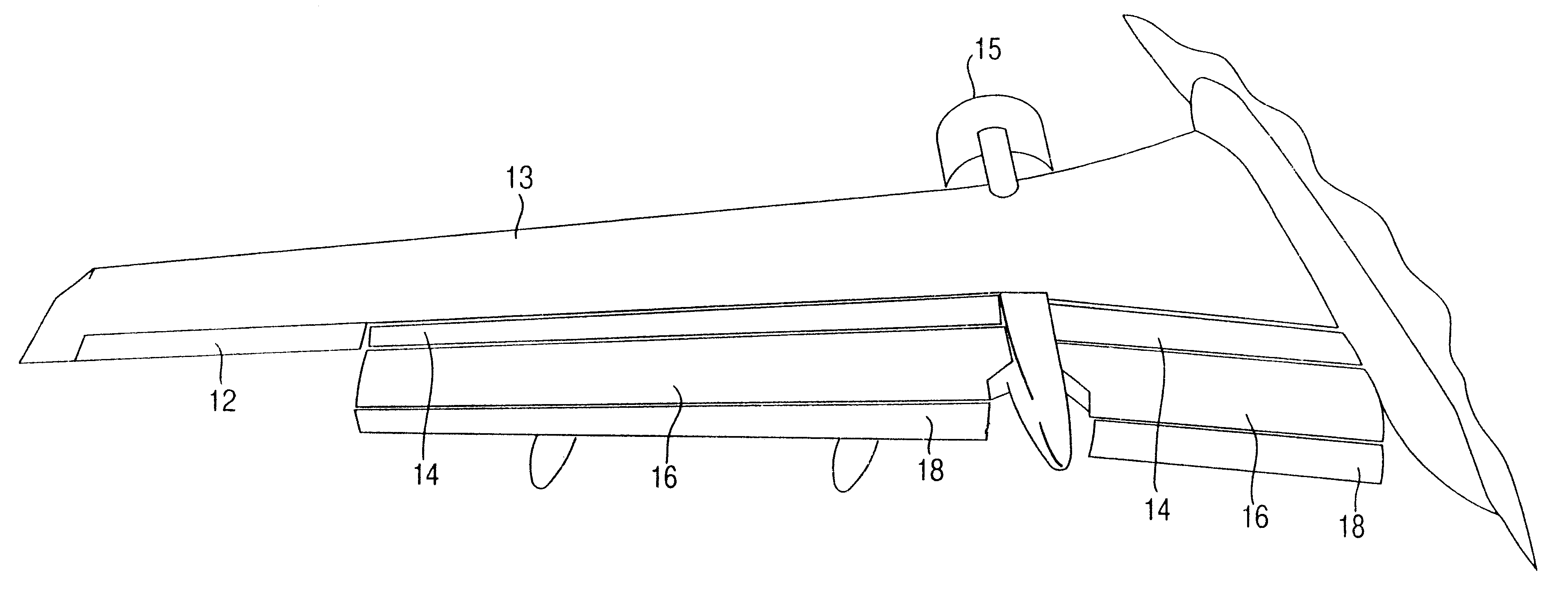
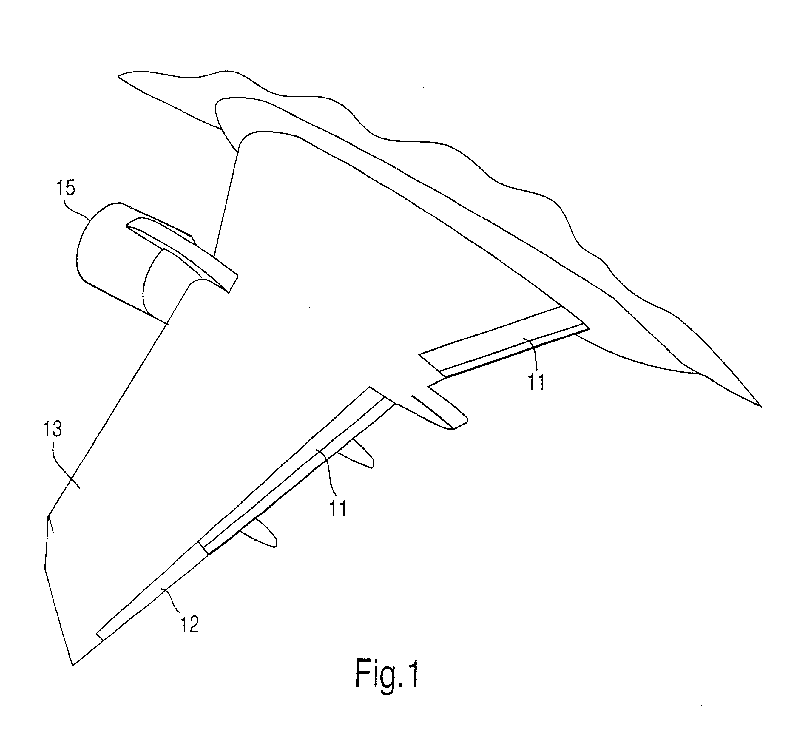
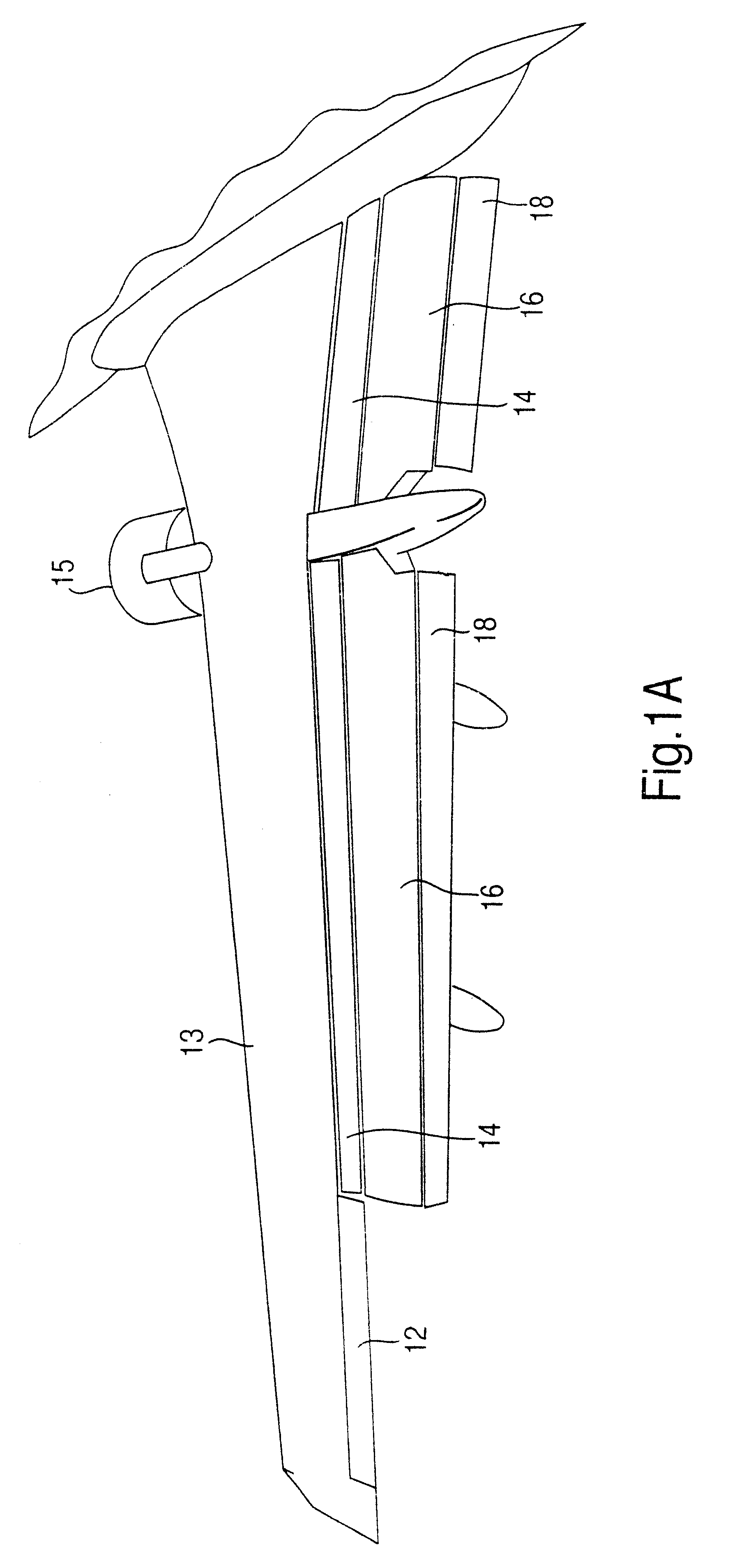
A preferred embodiment of the airfoil of the present invention employs a multi-segmented trailing edge flap system equivalent to the flap system of a Boeing 737 type aircraft. The association of the trailing edge flaps 11 and ailerons 12 to the aircraft wing 13 is depicted in FIG. 1. The trailing edge flaps 11 of the Boeing 737 aircraft are composed of a section inboard and a section outboard of the under-wing mounted powerplant 15. The inter-relationship of the trailing edge flap segments, (fore flap 14, mid flap 16, and aft flap 18), is illustrated in FIG. 2 and FIG. 2A. Each section of aft flap 18 is positioned by two push-pull rods 24, and transits on two aft flap tracks 28 installed in the mid flap 16.

The aileron neutral position 20 (FIG. 3) is altered to a predetermined position 21 situating the trailing edge of the aileron 12 below the unmodified neutral setting; utilizing standard maintenance and rigging practices for the aircraft involved.

The aft flap segments 18 are reloca...


PUM


Abstract

A method and means are provided for increasing the aerodynamic efficiency of an airfoil employed by an aircraft. The method utilizes the primary flight control surfaces (11) (12) contiguous to the airfoil's trailing edge and relocates these devices to novel positions (21) (23) resulting in an expanded cord and enhanced camber for the aircraft wing (13). Self-adjusting push-pull rods (25) (60) replace conventional solid rods (24) where necessary in combination with a re-rigging of the flight control surfaces (11) (12) to predetermined positions (21) (23). Any voids created by this modification between the shared upper and lower fluid flow surfaces of the aircraft wing (13) and its flight control surfaces (11) (12) are eliminated through the installation of appropriate structure (40) or seal (43). Thus the aircraft wing (13) retains a unique geometric profile as a usual configuration.

Description

FEDERAL RESEARCHNot applicable.1. Field of InvestigationThe present invention pertains to an aircraft wing or lifting airfoil that incorporates trailing edge flaps and ailerons as primary flight control surfaces; and improves the performance of said airfoil.More particularly, this invention addresses the geometry and camber of the airfoil profile and improves the overall aerodynamic efficiency of the airfoil during its operation by means of relocating the trailing edge devices to predetermined positions.In general, an airfoil is designed for a particular aircraft and the specific use of that aircraft. In most instances the lift and drag characteristics of any given airfoil can be further optimized using established aerodynamic principles.2. Description of Prior ArtIt is well known and extensively documented that changes in an airfoil's camber during various phases of flight produce optimal results. It has also been suggested that changing the shape of an airfoil's trailing edge, or ...

Claims


Application Information

Patent Timeline
Patent Type & Authority Patents(United States)
IPC IPC(8): B64C9/00B64C9/16B64C9/20B64C3/00B64C3/48
CPCB64C3/48B64C9/16B64C9/20Y02T50/145Y02T50/32Y02T50/10Y02T50/30
Inventor NETTLE, JAMES E.LORD, JAMES R.
Owner AEROTECH SERVICES
Why Eureka
Try Eureka