Microscopic geometry measuring device

a technology of geometry and measuring device, which is applied in the direction of mechanical measuring arrangement, electrical/magnetic diameter measurement, instruments, etc., can solve the problems of inability to accurately control the movement of the stylus, mechanical interference between the fine feed mechanism and the coarse feed mechanism, and difficulty in measuring force control

Inactive Publication Date: 2003-08-12
MITUTOYO CORP
View PDF17 Cites 33 Cited by
  • Summary
  • Abstract
  • Description
  • Claims
  • Application Information

AI Technical Summary

Benefits of technology

In order to eliminate the mechanical interference between the fine feed mechanism and the coarse feed mechanism, the mass of the fixed portion of the fine feed mechanism may be set sufficiently greater than the mass of the movable portion, so that the reaction force of the movable portion is absorbed by the fixed portion to block the force applied from the fine feed mechanism to the coarse feed mechanism. However, in this case, since the mass of the entire fine feed mechanism is increased and the mass applied on the movable portion of the coarse feed mechanism for the fine feed mechanism to be provided is increased, the responsivity of the coarse feed mechanism is lowered, so that the measurement speed cannot be increased.
Since the displacement sensor for detecting the movement of the stylus by the fine feed mechanism and the coarse feed mechanism is composed as a single component, the cost can be reduced.

Problems solved by technology

Since the control value range is too wide, the measuring force control has been difficult.
In other words, a mechanical interference is caused between the fine feed mechanism and the coarse feed mechanism.
When the mechanical interference is caused between the fine feed mechanism and the coarse feed mechanism, the stylus displaces in a complicated and uncontrollable manner, so that the measuring force cannot be controlled by an accurate control of the stylus movement.
Uncontrollable measuring force applied to the stylus results in deterioration in measurement accuracy and, possibly, damage on the workpiece and the stylus.
However, in this case, since the mass of the entire fine feed mechanism is increased and the mass applied on the movable portion of the coarse feed mechanism for the fine feed mechanism to be provided is increased, the responsivity of the coarse feed mechanism is lowered, so that the measurement speed cannot be increased.

Method used


Image

  • Microscopic geometry measuring device
  • Microscopic geometry measuring device
  • Microscopic geometry measuring device

Examples


first embodiment

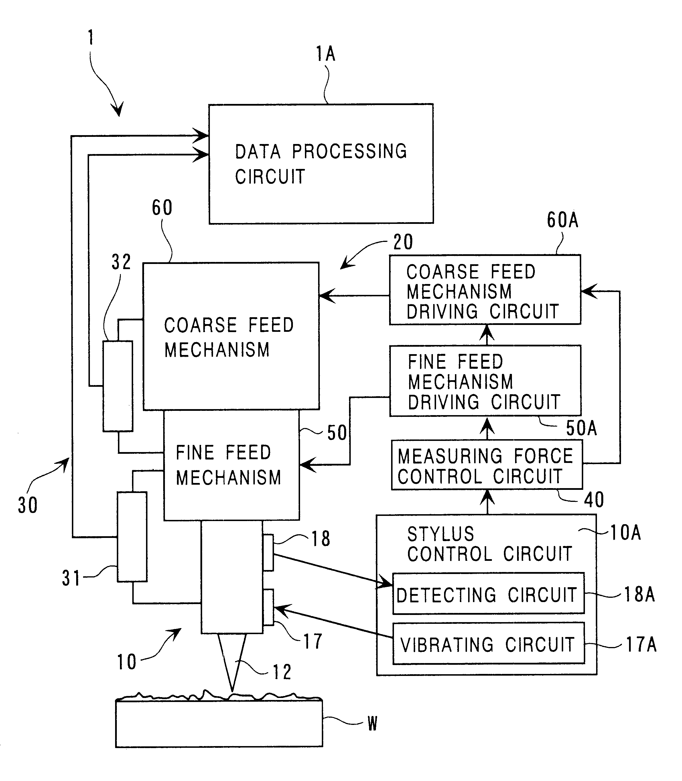
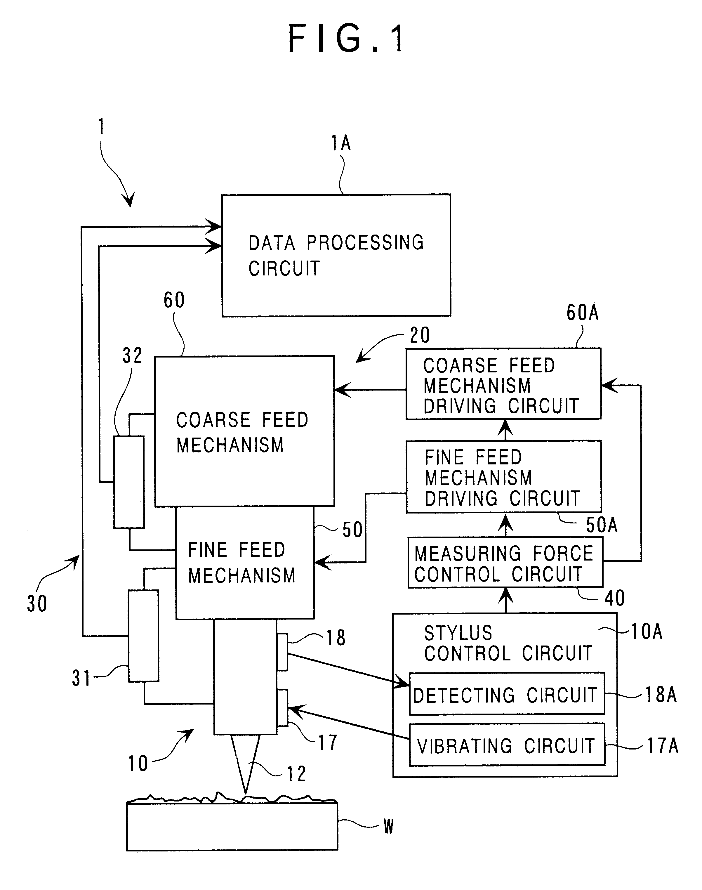
FIG. 1 is a general block diagram showing a microscopic geometry measuring device according to first embodiment of the present invention.

The measuring device 1 has a stylus mechanism 10 having a stylus 12 to be in contact with a workpiece W, a drive mechanism 20 for vertically (in height direction of the surface of the workpiece W) moving the stylus 12, a displacement sensor for detecting the movement of the stylus 12 by the drive mechanism 20, and a measuring force control circuit 40 for adjusting a measuring force applied to the stylus 12.

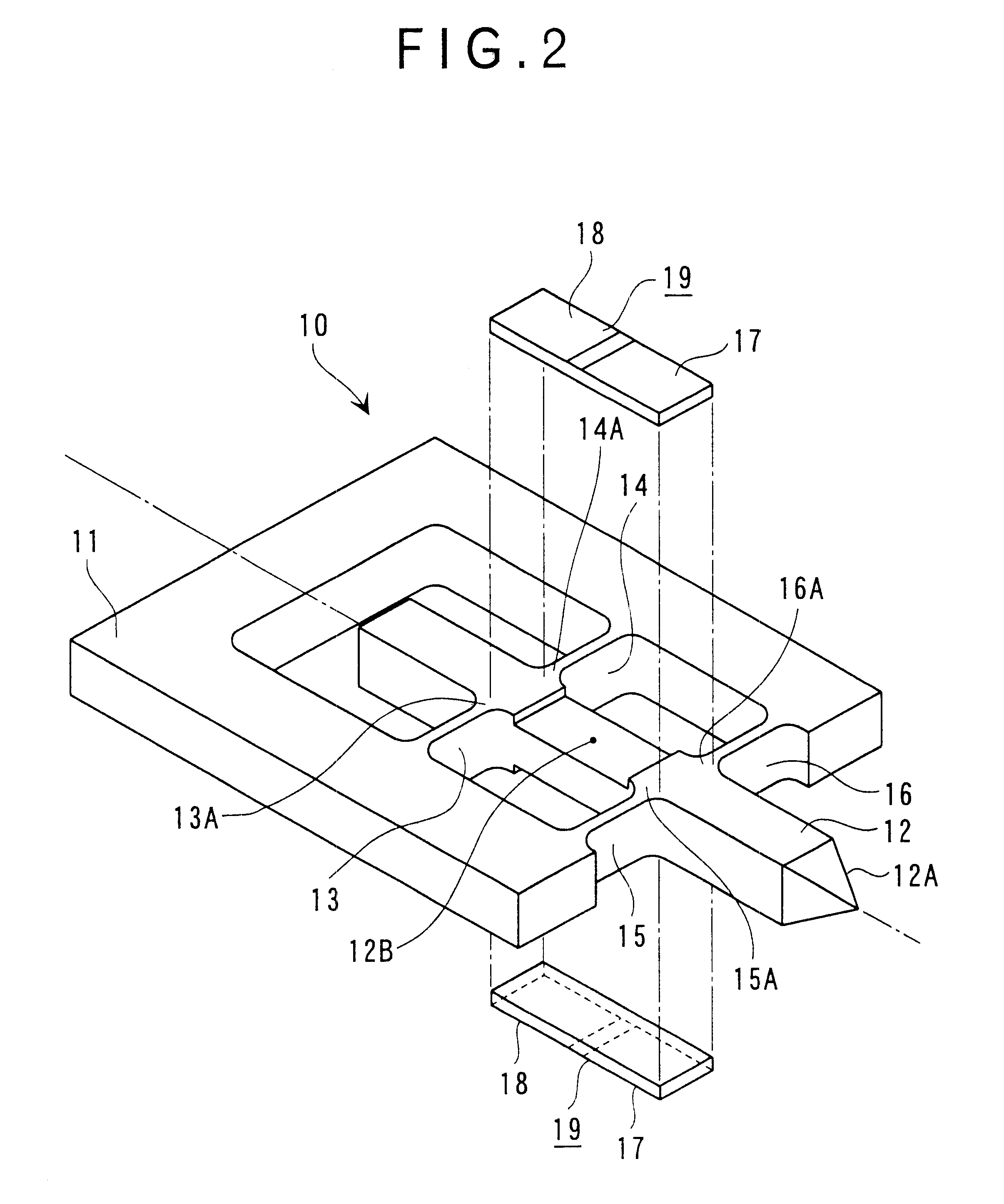
The stylus mechanism 10 has, as shown in FIG. 2, an approximately C-shaped holder 11, a stylus 12 having a contact portion 12A to be in contact with the workpiece W at the distal end thereof, the stylus 12 being supported by the holder 11 with a distal end protruding from an opening, four connecting members 13, 14, 15 and 16 for connecting the holder 11 and the stylus 12, a vibrator 17 for resonantly vibrating the stylus 12 in an axial direction ...

second embodiment

FIG. 4 shows a microscopic geometry measuring device 2 according to the second embodiment of the present invention. Since the present embodiment and the above-described first embodiment differ only in the arrangement of the coarse feed mechanism and the displacement sensor and the other arrangements and functions are the same, the same reference numeral will be attached to the same or similar components to omit or simplify the description therefor.

A coarse feed mechanism 70 vertically moves the fine feed mechanism 50 and the stylus 12 by vertically moving a movable coil 73 within a gap of a magnetic circuit composed of a yoke 71 fixed to a base (not shown) and a permanent magnet 72 and providing the fine feed mechanism 50 on the lower end side of the movable coil 73. A plate 74 is fixed to the lower end of the movable coil 73. The fixed portion 51 of the fine feed mechanism 50 is fixed to a support member 75 projecting downwardly from the plate 74, thus mounting the fine feed mechan...


PUM


Abstract

A fine feed mechanism (50) and a coarse feed mechanism (60) respectively for minutely and greatly displacing a stylus (12) is provided to a microscopic geometry measuring device (1), so that the respective mechanisms (50, 60) are combinedly actuated for easily controlling the movement of the stylus (12) in a wide range at a short time. Further, a movable balancing portion (53) moving in a direction opposite to a movable driving portion (52) is provided to the fine feed mechanism (50). Since a reaction force caused by the movement of the movable driving portion (52) is cancelled by another reaction force caused by the movement of the movable balancing portion (53) at a fixed portion (51), no mechanical interference is caused between the respective mechanisms (50, 60), thus accurately controlling the movement of the stylus (12).

Description

1. Field of the InventionThe present invention relates to a microscopic geometry measuring device. More specifically, it relates to a microscopic geometry measuring device for accurately measuring a surface profile of LSI (large scale integration) and other semiconductor wafers.2. Description of the Related ArtConventionally, in accurately measuring the surface profile of a LSI and other semiconductor wafer, it is strongly desired to maintain a measuring force applied between a workpiece and a stylus in contact with the surface of the workpiece below a predetermined level. This is because damage to the workpiece and to the stylus can be prevented and the surface profile of the workpiece can be accurately reflected on the movement of the stylus by keeping the measuring force below a predetermined level. In order to meet the demand, a specially designed measuring device provided with a mechanism for controlling the measuring force below a predetermined level is used in accurately meas...

Claims


Application Information

Patent Timeline
Patent Type & Authority Patents(United States)
IPC IPC(8): G01B7/12G12B21/00G12B21/22G12B21/20G12B21/08G12B21/02G01B21/30G01Q10/00G01Q10/04G01Q60/32G01Q80/00
CPCB82Y35/00G01B7/12G01Q10/02G01Q10/04G01Q10/065G01Q10/045G01Q20/04
Inventor NISHIMURA, KUNITOSHIHIDAKA, KAZUHIKOOKAMOTO, KIYOKAZU
Owner MITUTOYO CORP
Why Eureka
Try Eureka