Optical spectrum analyzer

a spectrum analyzer and optical spectrum technology, applied in the field of optical spectrum analyzers and monochromators, can solve the problems of inability to fully solve the problem of significant back-reflection into the input fiber, inability to easily compensate or take into account the beam expander, and the inevitable inherent wavelength-dependent polarization-dependent loss of components such as couplers, circulators and isolators

Inactive Publication Date: 2003-10-21
EXFO ELECTRO OPTICAL ENG
View PDF10 Cites 53 Cited by
  • Summary
  • Abstract
  • Description
  • Claims
  • Application Information

AI Technical Summary

Problems solved by technology

A disadvantage of their design arises from the fact that the light beam components are recombined and leave via the same exit port.
In general, the use of components such as couplers, circulators and isolators is accompanied by an inevitable inherent wavelength-dependent polarization-dependent loss, that cannot readily be compensated for, or taken into account.
A further disadvantage arises from the fact that the separation of the input beam into constituent, orthogonal polarization states occurs within the monochromator section of their design, where the light beams are propagating in free space.
This introduces a complication in the optical design and the choice of components, since the beam size may be limited by the clear aperture of the polarization beam splitter, which for cost and availability reasons should be kept as small as possible.
The addition of a beam expander (e.g. with anamorphic prisms) to avoid this problem would be unsatisfactory because it would be expensive and unwieldy.
However, this modification would not entirely solve the problem of significant back-reflection into the input fiber and would not reduce OSNR degradation caused by back scattering, whereby light scattered by components within the monochromator is received by the output fiber.
According to Lefevre et al., their optical spectrum analyzer is polarization insensitive. in practice, however, there is a wavelength-dependent loss resulting from polarization dependence of components used in their design, particularly the waveplate.
Although this wavelength-dependent loss can be compensated in the firmware of the analyzer, it results in a limitation in the ultimately attainable instrumental sensitivity.

Method used


Image

  • Optical spectrum analyzer
  • Optical spectrum analyzer
  • Optical spectrum analyzer

Examples


Embodiment Construction

:

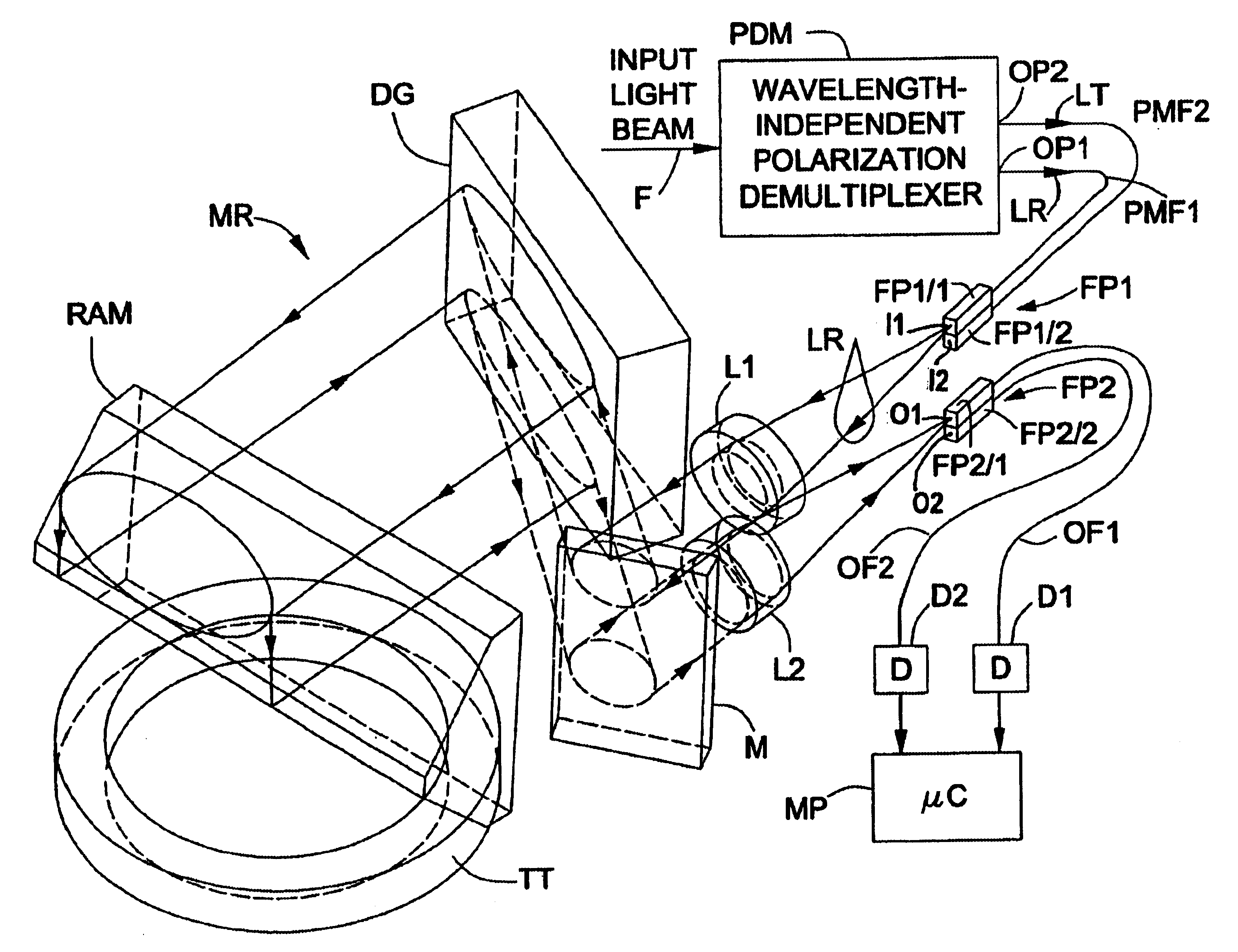
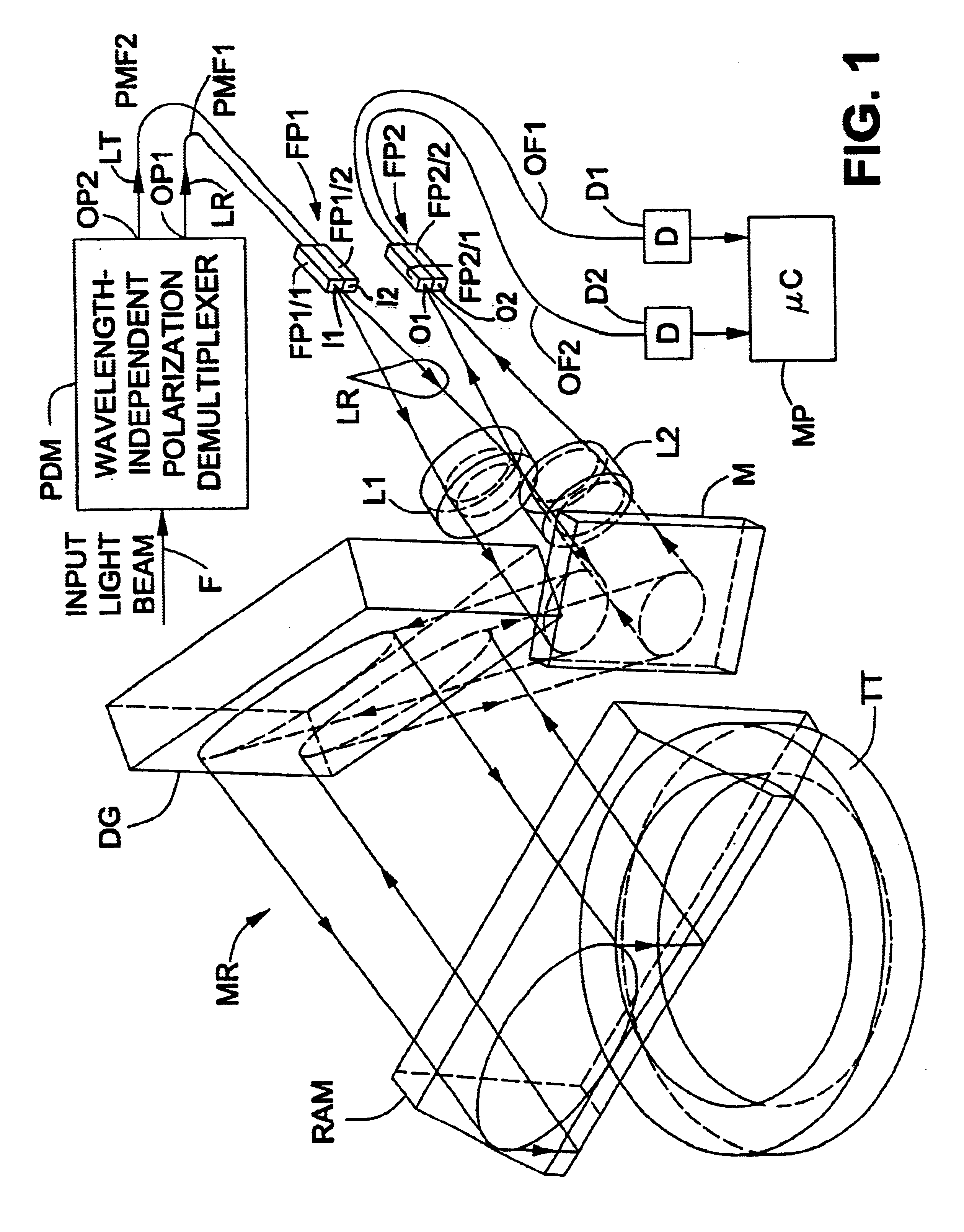
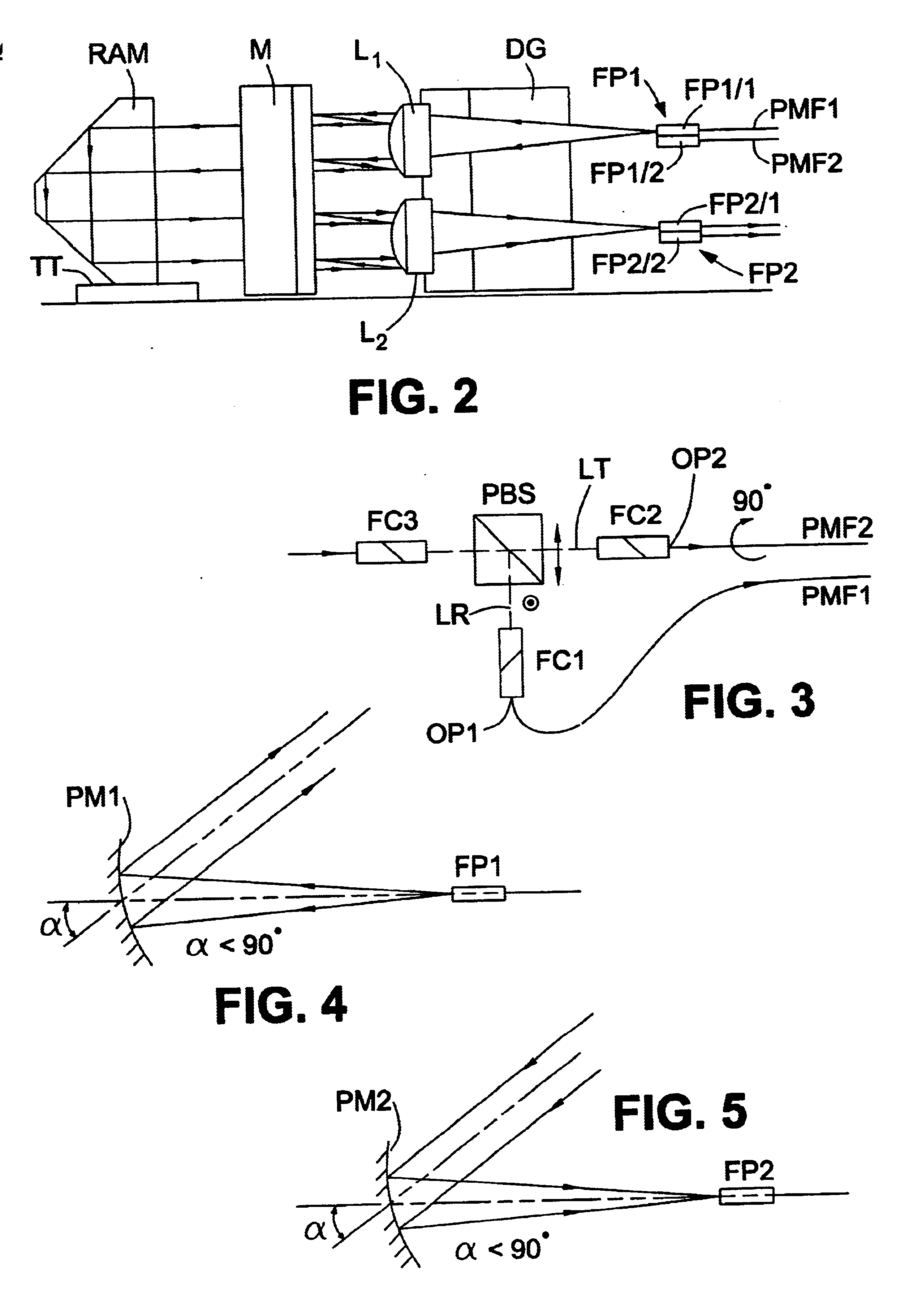
Referring first to FIGS. 1 and 2, an optical spectrum analyzer comprises a wavelength-independent polarization demultiplexer unit PDM (not shown in FIG. 2) and a monochromator section MR. As shown in FIG. 1, the wavelength-independent polarization demultiplexer PDM has an input port to which the input light beam for analysis is supplied via an optical fiber F and two output ports OP1 and OP2 for first and second light beams LR and LT, respectively, having mutually orthogonal linear states of polarization. The output ports OP1 and OP2 are coupled to the monochromator section MR by polarization-maintaining (PM) fibers PMF1 and PMF2, respectively, for conveying the first and second light beams LR and LT to the monochromator section MR. The two PM fibers PMF1 and PMF2 may be single mode or multi-mode at the wavelengths of operation. The birefringence axis of the second polarization-maintaining fiber PMF2 is twisted through 90 degrees relative to that of the first polarization-maintaini...


PUM


Abstract

An optical spectrum analyzer comprises a diffraction grating (DG), a polarization decomposing unit (PDM) for decomposing the input light beam into first and second light beams having mutually-perpendicular linear states of polarization, and two output ports (FP2 / 1, FP2 / 2) each for receiving from the grating, substantially exclusively, a respective one of the polarized light beams (LT, LR) after diffraction by the diffraction grating (DG). Each of the linearly-polarized light beams is directed onto the diffraction grating with its linear state of polarization at any prescribed angle to a corresponding plane of diffraction of the diffraction grating The arrangement is such that the state of polarization of the light beams, at any particular wavelength within an operating band of the analyzer remains substantially unchanged with respect to time, The analyzer also may have a reflector (RAM) for reflecting the light beams leaving the diffraction grating after diffraction a first time so as to return them to the diffraction grating for diffraction a second time.

Description

DESCRIPTION1. Technical FieldThis invention relates to optical spectrum analyzers and monochromators of the kind which use a diffraction grating. The invention is especially applicable to optical spectrum analyzers in which the light beam to be analyzed is applied to the diffraction grating more than once so as to obtain improved resolution, and to monocchromators for use therein.2. Background ArtThe invention is concerned especially with an optical spectrum analyzer of the kind disclosed in U.S. Pat. No. 5,986,785 issued March 1999 naming H. Lefcvre et al. as inventors. Lefevre et al. disclosed an optical spectrum analyzer comprising a diffraction grating and a dihedral reflector. The input light beam for analysis is received via an input / output port, collimated, and passed through a polarization splitter which splits the light beam into two linearly-polarized components having their respective directions of linear polarization mutually perpendicular. The transmitted beam is passed...

Claims


Application Information

Patent Timeline
Patent Type & Authority Patents(United States)
IPC IPC(8): G01J3/447G01J3/12G01J3/28
CPCG01J3/447G01J3/12
Inventor HE, GANGGARIEPY, DANIELSCHINN, GREGORY WALTER
Owner EXFO ELECTRO OPTICAL ENG
Why Eureka
Try Eureka