Valve with self-cleaning trim

a valve and self-cleaning technology, applied in mechanical equipment, functional valve types, transportation and packaging, etc., can solve the problems of premature wear of the trim set, adversely affecting the valves ability to seal properly, and abrasive liquid flowing to the valve, so as to achieve the effect of minimizing damage to the seating surfa

Inactive Publication Date: 2003-10-28
FISHER CONTROLS INT LLC
View PDF11 Cites 73 Cited by
  • Summary
  • Abstract
  • Description
  • Claims
  • Application Information

AI Technical Summary

Benefits of technology

As a result of its placement between the seat and the distal end of the plug, the wiper seal engages the seating surface before the seat as the plug is moved from a throttle to a sealed position. Further, as the seat of the plug is moved off of the seating surface as the plug is moved from the sealed to a throttle position, the wiper seal again engages the seating surface and, further, engages a remaining portion of the seal ring and further engages a distal or upstream end of the cage before the plug reaches an initial throttle position. As a result, the wiper seal cleans the seating surface and the upstream portion of the cage when the plug is moved from a throttling to a sealed position and further when the plug is moved from a sealed position to an initial throttling position.
In a refinement, the wiper seal comprises a material sufficiently rigid to scrape foreign material from the seating surface as the plug moves in either axially direction and further the material of the wiper seal is sufficiently resilient to minimize damage to the seating surface of the sealing ring and the interior surface of the cage.
In another refinement, the wiper seal is an elastic seal that is biased radially outwardly to provide good engagement between the wiper seal and the seating surface as well as the interior surface of the cage.
FIG. 5 is another partial expanded view of the valve shown in FIGS. 1 and 2 illustrating further upward axial movement of the valve plug and illustrating engagement of the wiper seal against the sealing ring which prevents throttling even though the seat of the valve plug no longer engages the seating surface of the seal ring;

Problems solved by technology

One problem associated with currently available valve systems is that the fluid flowing to the valve can contain abrasive particles and fluids that can crystallize during pressure reduction.
These particles and crystals can cause premature wear to the trim set or adversely affect the valves ability to seal properly.
While some valve systems incorporate so-called wiper seals to clean the valve trim, these known wiper seal systems do not clean the valve trim immediately before and after sealing.
Further, known wiper seals do not protect the seating surfaces from being exposed to fluid flow as the valve is initially opened.
As a result, the seating services are exposed to high pressure flow which, as discussed above, can contain abrasive particles and crystals resulting in premature seating surface wear.

Method used


Image

  • Valve with self-cleaning trim
  • Valve with self-cleaning trim
  • Valve with self-cleaning trim

Examples


Embodiment Construction

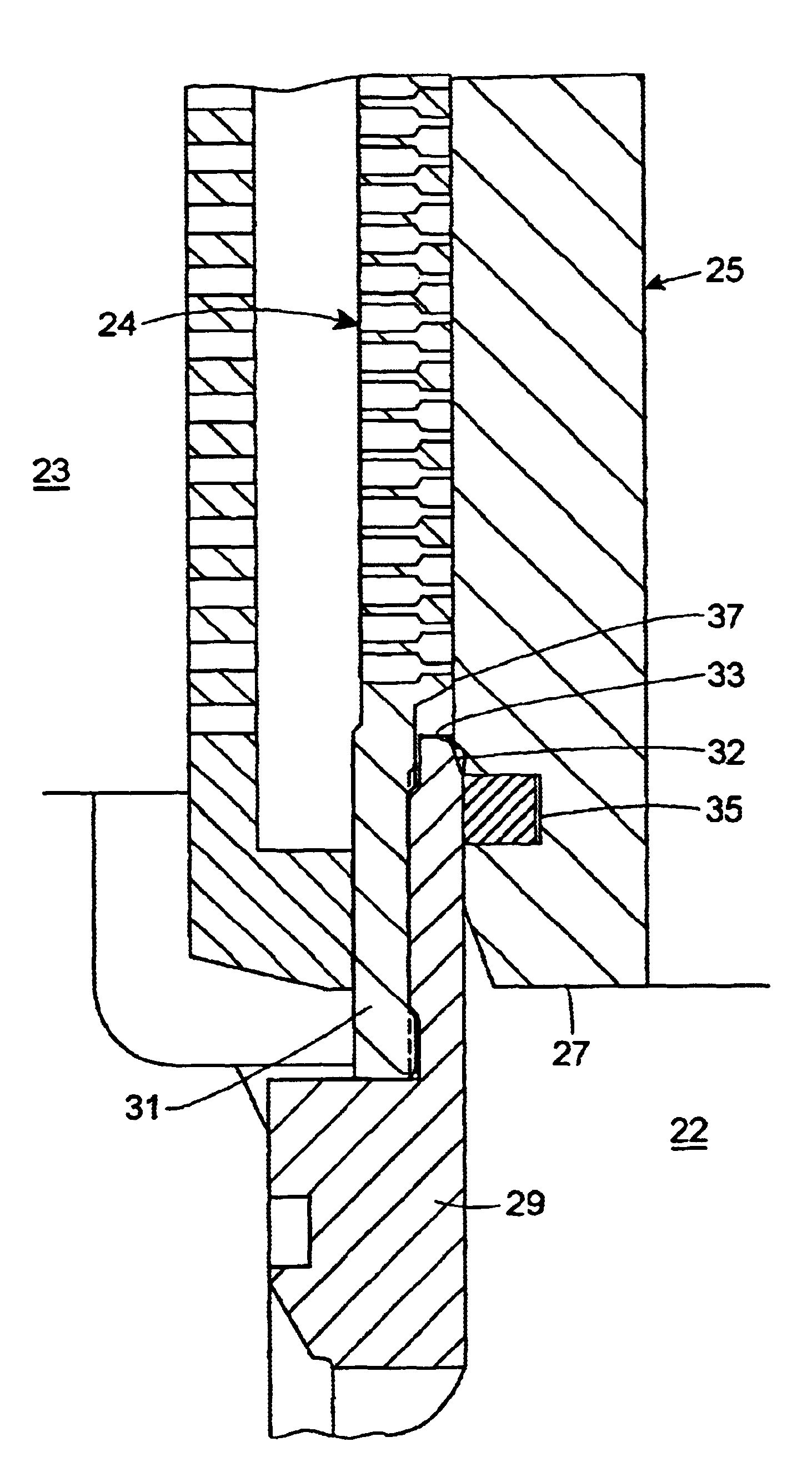
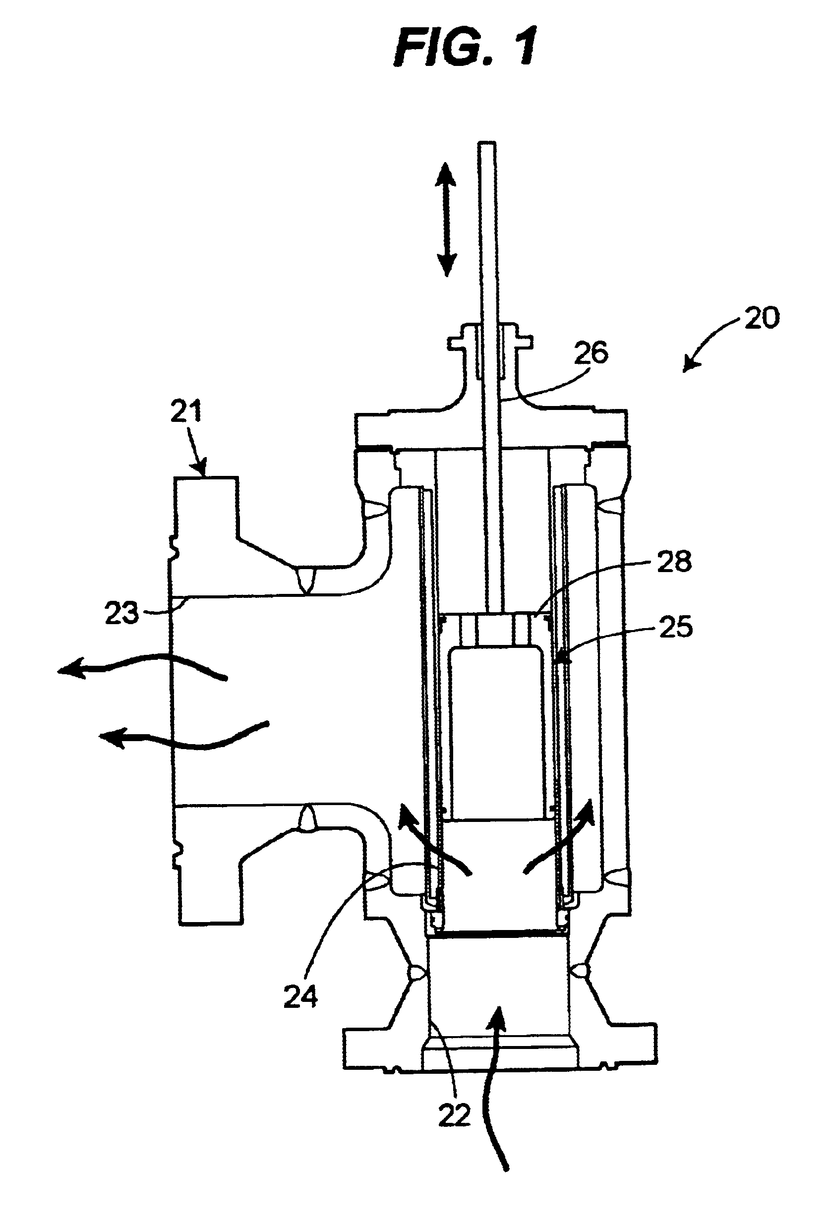
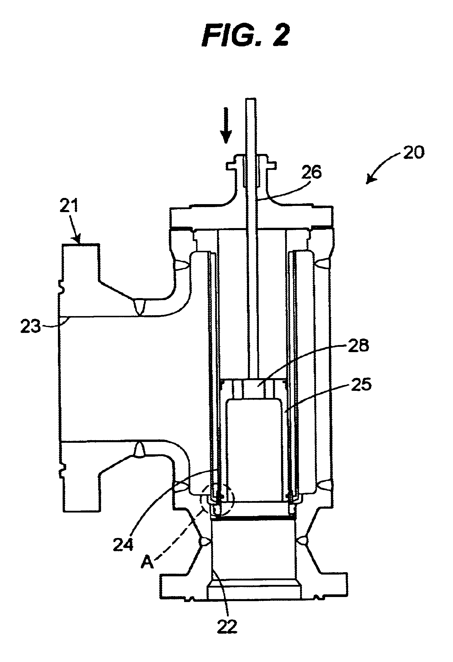
FIGS. 1 and 2 illustrate a valve 20 with a valve body 21 that includes an inlet 22 and an outlet 23. Fluid flows through the valve body 21 in the direction indicated by the arrows. To control fluid through the valve body 21, a permeable cage 24 is disposed between the inlet 22 and 23. A valve plug 25 is accommodated within the axial bore defined by the cage 24. The plug 25 is connected to a stem 26 which, in turn, is connected to an actuator (not shown) for moving the plug 25 between an open or throttle position as shown in FIG. 1 in a closed or sealed position as shown in FIG. 2. The detail A which illustrates the sealing, cleaning and throttling aspects of the valve 20 is further illustrated in FIGS. 3-8.

Turning to FIGS. 3-8, movement of the valve plug 25 from the closed or sealed position (FIG. 3) to an open or throttling position (FIG. 8) will now be described. Turning first to FIG. 3, the plug 25, which includes a upstream or distal end 27 and a downstream or proximal end 28 (s...


PUM


Abstract

The seal assembly is disclosed for use with a valve having a trim cage with an inner surface extending along in axis and a plug sized to fit inside the trim cage inner surface, wherein the plug is adapted to move along the axis thereof. A seal ring is attached to an upstream portion of the cage to effectuate a seal with the plug. The plug is equipped with a wiper seal that cleans or otherwise removes debris from the seating surface of the seal ring, an interior surface of the seal ring and an interior surface of the cage during both the opening and the closing of the valve. Thus, the valve is self-cleaning. Further, the wiper seal delays throttling action through the valve until the plug has moved a substantial distance away from the seating surface of the seal ring which reduces high pressure abrasive flow against the seating surface of the seal ring to reduce wear on the trim set.

Description

1. Technical FieldAn improved fluid valve system is disclosed. More specifically, an improved valve is disclosed which includes a valve plug that is slidably received within a bore defined by a cage. A seal ring is connected to the cage and engagement with the valve plug against the seal ring closes the valve. The valve plug is equipped with a wiper seal that cleans the trim set of debris and residue each time the valve moves between opened and closed positions. As a result, the valve is equipped with a self-cleaning trim set.2. Background of the Related ArtValves are commonly used to control the flow characteristics of a fluid. A conventional valve includes a valve body defining an inlet, an outlet, and a fluid flow path extending between the inlet and the outlet. A throttling element, such as a plug, is disposed in the path to control fluid flow. A stem connects the valve plug to an actuator, which moves the valve plug into and out of the flow path. A conventional valve may includ...

Claims


Application Information

Patent Timeline
Patent Type & Authority Patents(United States)
IPC IPC(8): F16K3/24F16K3/00F16K47/08F16K47/00
CPCF16K47/08F16K3/243Y10T137/4336Y10T137/86734Y10T137/86791
Inventor ALMAN, PAUL T.
Owner FISHER CONTROLS INT LLC
Why Eureka
Try Eureka