Illuminated showerhead

a shower head and shower head technology, applied in the direction of burners, boring tools, light guides details, etc., can solve the problem of inefficient light transmission

Inactive Publication Date: 2003-10-28
WATER PIK INC
View PDF18 Cites 135 Cited by
  • Summary
  • Abstract
  • Description
  • Claims
  • Application Information

AI Technical Summary

Problems solved by technology

At least one problem with this design is that it is inefficient in the transmission of light because the common cavity generally receives light from the source of illumination and there is no direct coupling to each of the shower sprays or openings through which water is transmitted.

Method used


Image

  • Illuminated showerhead
  • Illuminated showerhead
  • Illuminated showerhead

Examples


Embodiment Construction

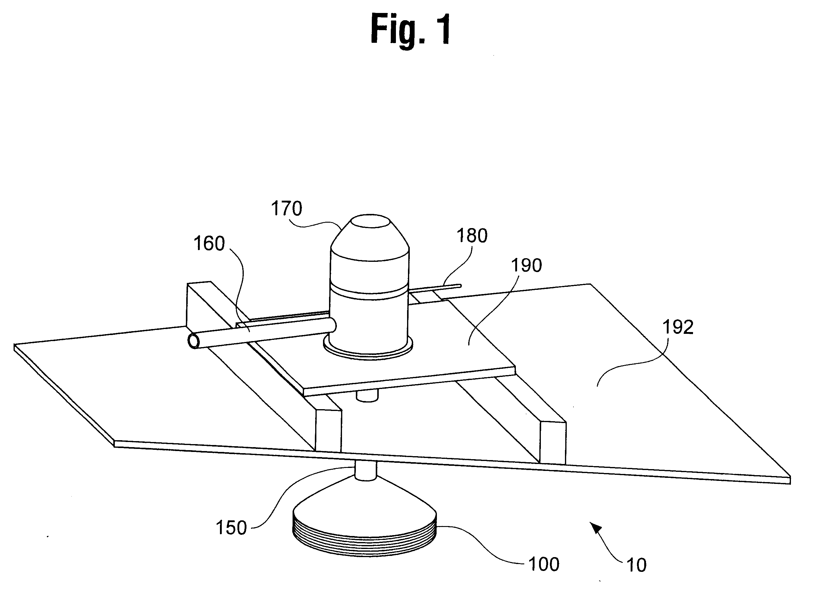
FIG. 1 illustrates a first exemplary embodiment of the present invention which is shown generally at 10. As shown in FIG. 1, a showerhead 100 is supported from above and supplied with water via a supply pipe 150. A standard water supply pipe or plumbing line 160 supplies water to the showerhead and fixture assembly. A light source is located within fixture assembly 170 and provides a source of illumination which generates light that is transmitted through showerhead 100. Electrical power is supplied to the light source 170 through a typical electrical wire 180. A support plate 190 may be used to secure the showerhead and fixture assembly in the ceiling of a shower stall. As shown in FIG. 1, the support plate 190 may be secured to conventional ceiling joists or other supports above the shower ceiling 192.

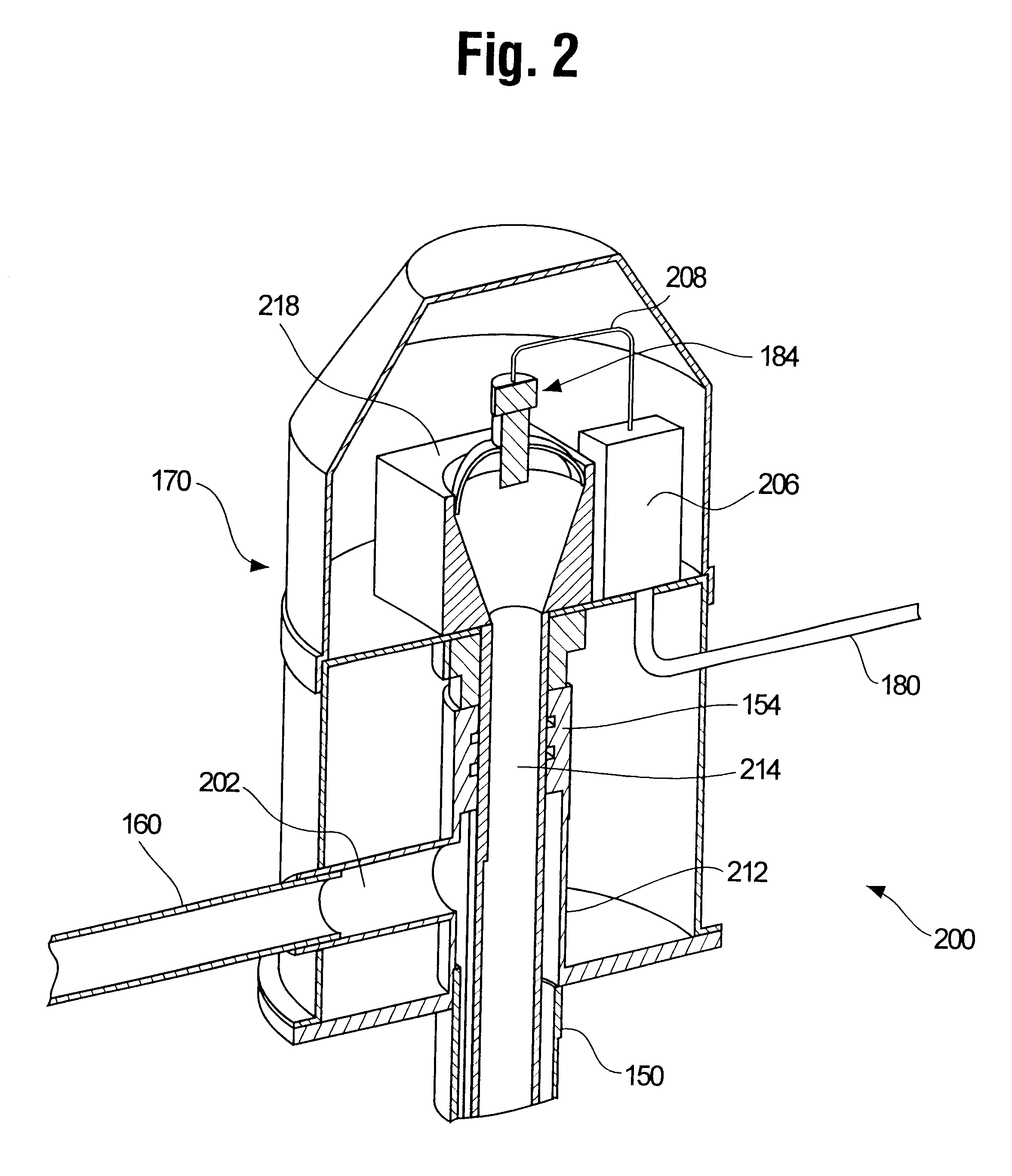
FIG. 2 illustrates the details of the shower head fixture assembly which is shown generally at 200. As shown in FIG. 2, supply line 160 may be connected to the showerhead fixture ass...


PUM


Abstract

A showerhead which may be utilized as a source of illumination includes a source of illumination which is efficiently coupled to individual ones of a plurality of water sprays. In an exemplary embodiment, a plurality of fiber-optic members transmit light from one or more individual light sources to corresponding ones of a plurality of individual shower sprays or nozzles. Light from the source of illumination is thus transferred to and is transmitted through a plurality of individual water sprays.

Description

1. Field of the InventionThe present invention relates generally to the field of shower fixtures and water spraying mechanisms. More specifically, the present invention is directed to shower heads and fixtures which include, sources of illumination to incorporate light into the streams of water flowing from the shower head or water spraying mechanisms.2. Description of the Related ArtThere are currently a wide variety showerhead and water spraying fixtures which are commercially available and known in the prior art. Known showerhead devices and water spray mechanisms include both handheld and fixed devices. The wide variety of known showerhead water spray fixtures includes mechanisms for adjusting both the type of spray as well as the amount water flowing through the device. The market for high-end showerhead devices and water spray mechanisms is highly competitive and manufacturers are continuously looking for unique features which will distinguish their products from those of thei...

Claims


Application Information

Patent Timeline
Patent Type & Authority Patents(United States)
IPC IPC(8): B05B15/00B05B17/00B05B17/08B05B1/18F21V33/00F21V8/00F21S8/00
CPCB05B1/18B05B15/00B05B17/08F21V33/004F21V2200/10F21W2121/02F21W2131/401
Inventor ZIEGER, CLAUS D.ZIEGER, HENNIG
Owner WATER PIK INC
Why Eureka
Try Eureka