Modular test tube rack

a module and test tube technology, applied in the field of modules, can solve the problems of easy falling, voluminous 96 position models, and high cost of double inventory, and achieve the effect of convenient stacking

Inactive Publication Date: 2003-11-04
3088081 CANADA
View PDF24 Cites 126 Cited by
  • Summary
  • Abstract
  • Description
  • Claims
  • Application Information

AI Technical Summary

Benefits of technology

It is an object of the present invention to overcome the problems associated with presently used racks. This is achieved by providing a modular test tube rack for easy stacking assembly with similarly constructed racks.
a pair of handles respectively mounted at opposite end walls; each handle having a lower portion having means adapted to tightly engage the extension of the end wall of the body and to extend vertically therefrom; each handle having a hand gripping upper portion displaying a top edge; the lower portion of the handle having a bottom edge configured to anchor with the top edge of an underposed similarly constructed rack thereby enabling a stacking of two or more of the racks.

Problems solved by technology

The 96 position models are voluminous and take a lot of place on working tables.
Also, this double inventory is expensive.
This results in an unstable assembly where the tubes may easily fall and break their contents lost and the storing space contaminated.

Method used


Image

  • Modular test tube rack
  • Modular test tube rack
  • Modular test tube rack

Examples


Embodiment Construction

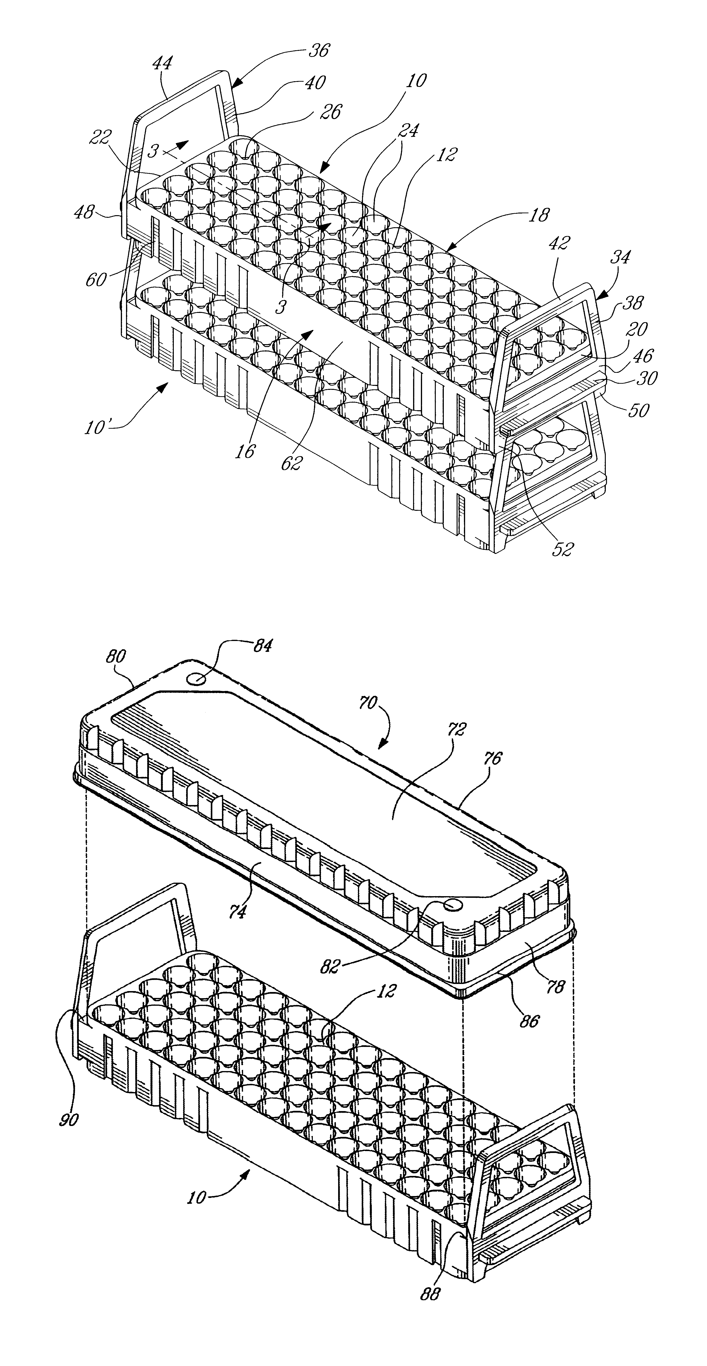
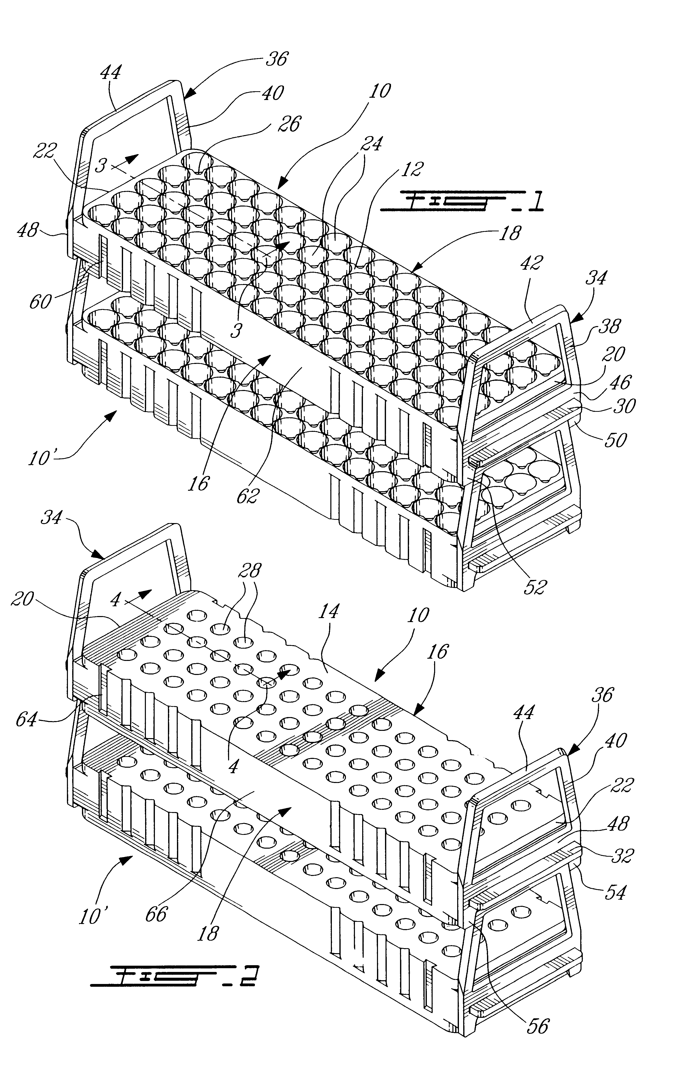
Referring to FIGS. 1 and 2, there are shown two stack racks 10, 10' which are identically constructed. Rack 10 consists of a flat rectangular body having a top wall 12, a bottom wall 14, opposite sidewalls 16 and 18 and opposite end walls 20 and 22.

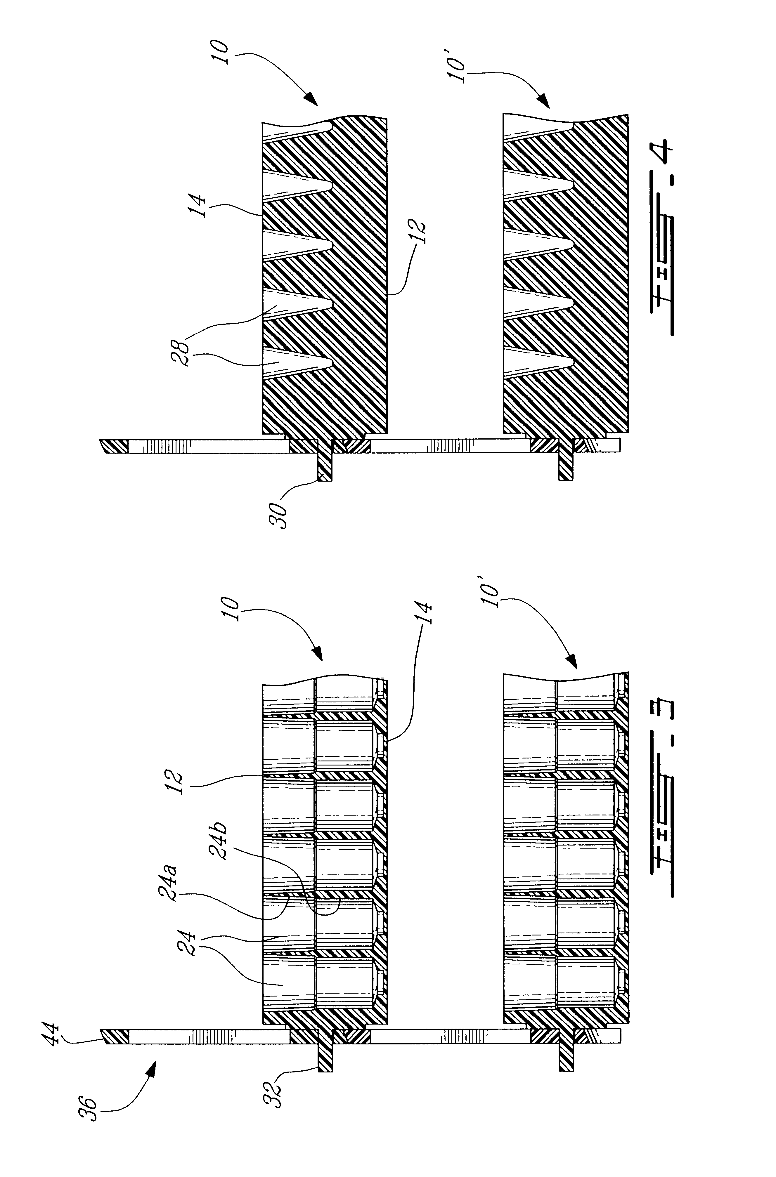
The top wall 12 displays a series of wells 24 disposed in rows and columns (80 wells being illustrated in the rack of FIG. 1). Each well has a small recess area 26 in its top wall so that numbers or letters (not shown) may be imprinted to identify the location of each well on the top wall. As can also be seen in FIG. 3, the wells 24 has a slightly tapered inner wall to receive test tubes for analytical purposes; also, they comprise two areas 24a and 24b having varying diameters to receive tubes of different outer diameters, for example 12 and 13 mm whereby the 12 mm tubes are less likely to become loose if they were received in a well which would have only an area 24a throughout its height.

The rectangular body of racks shown in FIG. 2 hav...


PUM


Abstract

A modular test tube rack for assembly with similarly constructed racks comprise a flat rectangular body displaying, in a first position, a series of wells extending from its top wall to its bottom wall and adapt to receive tubes therein. A pair of handles vertically extend at opposite end walls of the body, each handle having a lower portion adapted to tightly engage an extension on each end wall and a hand gripping upper portion. The lower portion has a bottom edge configured to anchor with the top edge of the handle of an underposed similarly constructed rack to thereby enable a stacking of two more of these racks. In one embodiment, the body displays a second series of wells extending from the bottom wall to the top wall whereby the body, when in a second position reversed relative to the first position, may also receive test tubes, the handles being reversably mountable to the end wall extension to still enable a stacking of racks in the second position.

Description

The present invention relates to a modular test tube rack configured for assembly with similarly constructed racks.Test tube racks are found in laboratories and serve to hold test tubes during various analytical and processing procedures.Racks may be arranged in modular fashion so that a plurality of these racks can be handled as a single rack. It has been found useful to provide handles which can be connected to the rack arrangement to facilitate transportation thereby eliminating the use of trays or other handling devices.One example of a modular test tube rack arrangement may be found described in U.S. Pat. No. 5,169,603 issued Dec. 8, 1992 to Landsberger in which a plurality of test tube racks are disposed side by side and coupled together at opposite sides by means of clamps to form a modular test tube rack arrangement. Handles engage the clamps to provide a balanced pivot handle arrangement for transporting the modular set of connected racks. Other modular tube rack arrays hav...

Claims


Application Information

Patent Timeline
Patent Type & Authority Patents(United States)
IPC IPC(8): B01L9/00B01L9/06
CPCB01L9/06B01L2300/0809B01L2300/02B01L2200/025
Inventor LAFOND, ANDREBERTIN, YANICK
Owner 3088081 CANADA
Why Eureka
Try Eureka