

Multi-functional floor-cleaning tool
a multi-functional, floor-cleaning technology, applied in the direction of carpet cleaners, floor surfacing/polishing machines, cleaning using liquids, etc., can solve the problems of contaminated mop bucket systems, difficult to maintain facility cleanliness, and increasing the number of dirty mop and "cleaning water"
Inactive Publication Date: 2003-11-18
KAIVAC
View PDF23 Cites 83 Cited by
- Summary
- Abstract
- Description
- Claims
- Application Information
AI Technical Summary
Problems solved by technology
This is particularly true for areas such as restrooms, locker rooms, cafeterias, food service kitchens, patient rooms, waiting rooms, factory floors, and other high-traffic areas, where the volume of traffic in the particular area may make it difficult to maintain the cleanliness of the facility.
However, as soon as the worker makes a first pass and wrings the mop out, the entire mop bucket system is contaminated.
From that point on, each time the worker plunges the mop into the bucket and rings the mop out, both the mop and "cleaning water" become more and more dirty.
However, this adds time to an already laborious process, and therefore, there is little worker incentive to make frequent water and mop changes.
In reality, however, given the limitations of these tools, the worker still is simply pushing dirt around the floor, as evidenced by the "five-o'clock shadow" of dirt seen frequently along the surface of walls adjacent the floor, as well as the "finger painting-like streaks" left by the mop when the water on the floor dries.
The cleanliness problem may be especially severe in the restrooms of these various buildings, and in fact, the number-one building maintenance complaint is dirty restrooms.
Given the frequency with which these facilities are used, as well as the tools available for cleaning restrooms, the dirty restrooms complaint is not particularly surprising.
And, as noted above, while this system may pick up some dirt, it tends more typically to spread dirty water around on the floor.
In addition, the mop-and-bucket system simply does not "cut it" when comes to dealing with greasy, slippery kitchen floors.
And because the group lines tend to hold onto grease and other soils even more tenaciously than the tiles themselves, it has been extremely difficult, if not impossible, to thoroughly clean such kitchen floors.
However, because of the limitations of several of these tools, as well as their single-task focus, sanitary maintenance professionals tend to use them in actual cleaning either infrequently, or not at all.
Most pressure washers operate at a pressure of 1000 PSI and above, a pressure which is far too high for many cleaning applications.
For example, if such a pressure washer were use to mechanically clean a painted wall, it would blast the paint off of the wall surface.
Although such a low-pressure washer may be beneficial in applying a cleaning solution, it lacks the mechanical power required to actually clean a particular surface once the solution has been applied.
Because pressure washers generally include a single clean-liquid water tank or container, both cleaning chemicals and water are loaded into this same container, which may be damaging to the device, particularly if a harsh cleaning chemical passes through a mechanical component, such as a pump.
Moreover, these pressure washers generally lack a convenient on-board storage system for storing the garden hose and power cord during transport.
However, movement of these devices from place to place can be difficult because the vac hose, wand, and various tools typically must be carried independently of the wet-vac device.
However, these tools are either inadequate to do a proper cleaning job, or are so task-specific that they become user-unfriendly, given the many aspects involved in proper sanitation maintenance.
Accordingly, given the relative ineffectiveness and / or inefficiency of the various tools available, particular facilities are not cleaned as well or as frequently as they should be, and morale and job satisfaction among many building maintenance professionals are relatively low.
Method used
View moreImage
Smart ImageViewing Examples

Examples
Embodiment Construction
. Therefore, the invention, in its broader aspects, is not limited to these specific details, representative apparatus and methods, and illustrative examples shown and described. Accordingly, departures may be made from such details without departing from the spirit or scope of the inventor's general inventive concept.
Login to View More PUM
 Abstract
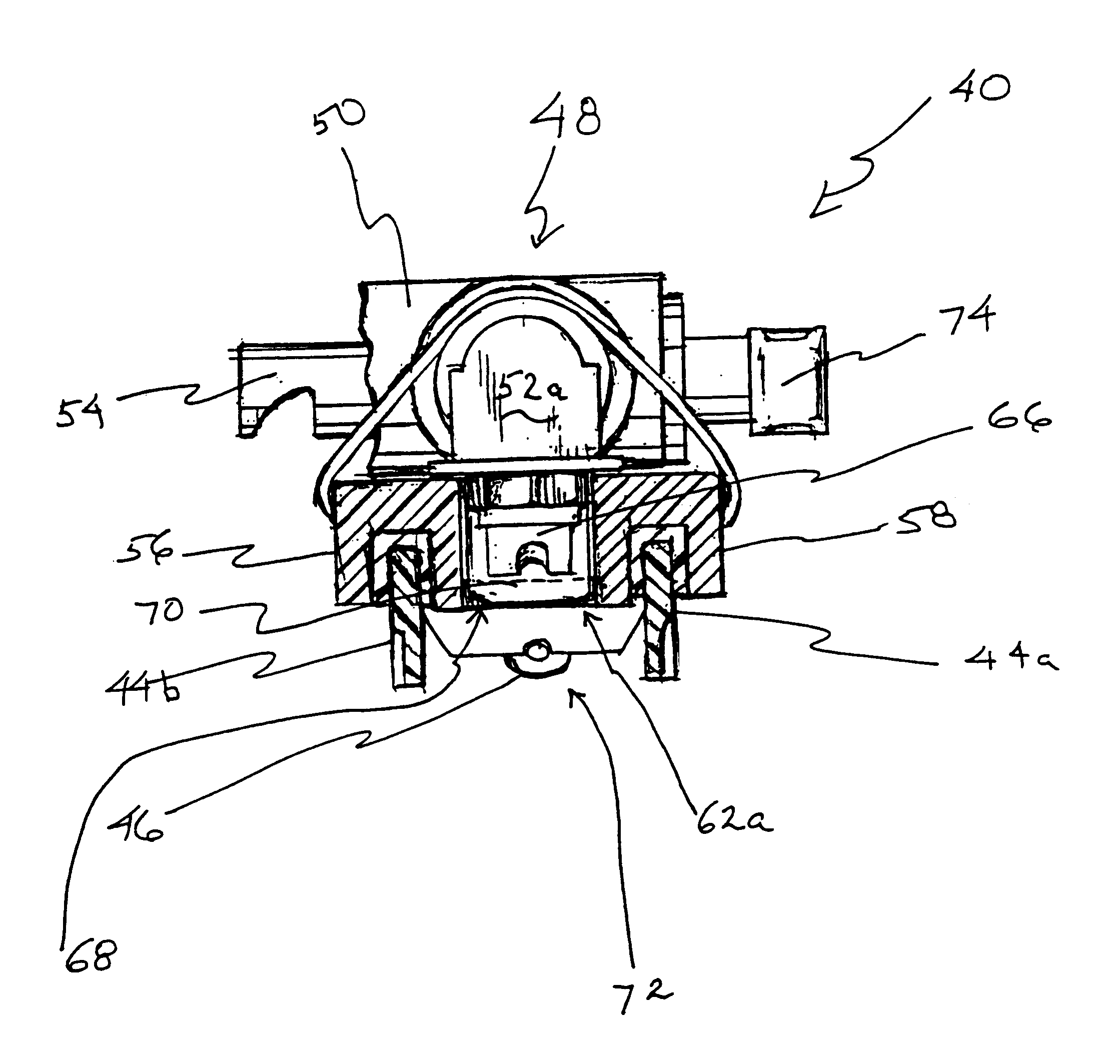
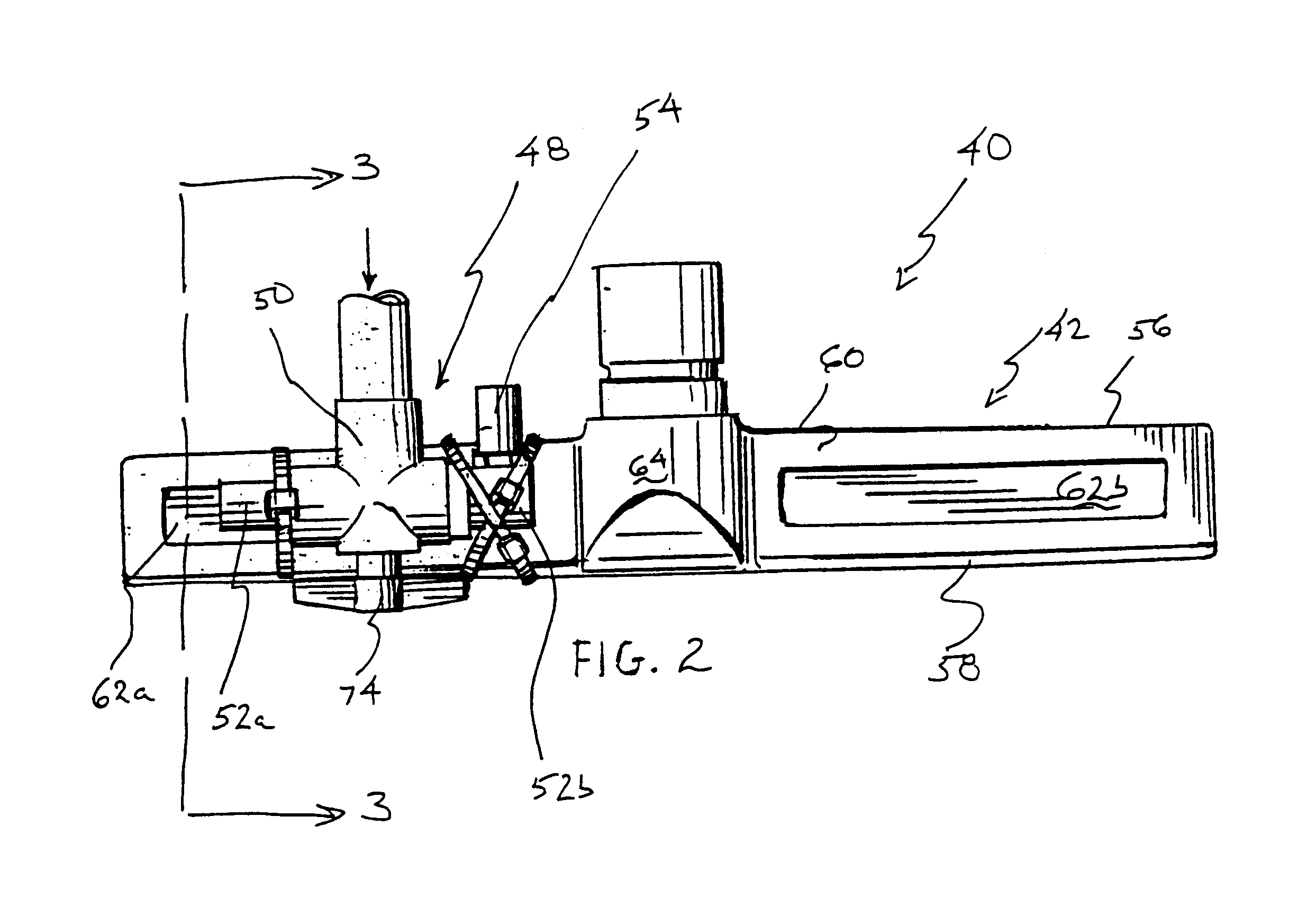
In one aspect of the invention, the tool includes: a housing having a front wall, a back wall, a top wall connecting the front and back walls, an interior surface, a liquid-delivery opening, and a soil-uptake opening, the soil-uptake opening being connectable to a vacuum source; a first squeegee blade depending from the front wall; a second squeegee blade depending from the back wall; an interior space defined by the interior surface, first squeegee blade, and second squeegee blade; a diverter valve connected to the housing, the diverter valve having at least an inlet, a first outlet, a second outlet, and a diverter, the diverter capable of selectively directing the flow of a pressurized liquid from the inlet to either the first outlet or the second outlet, the diverter valve being connectable to a pressurized-liquid source; a high-pressure nozzle connected to the first outlet of the diverter valve, the high-pressure nozzle constructed and arranged to deliver a liquid into the interior space via the liquid-delivery opening; and a low-pressure nozzle connected to the second outlet of the diverter valve, the low-pressure nozzle constructed and arranged to deliver a liquid exterior to the interior space.
Description
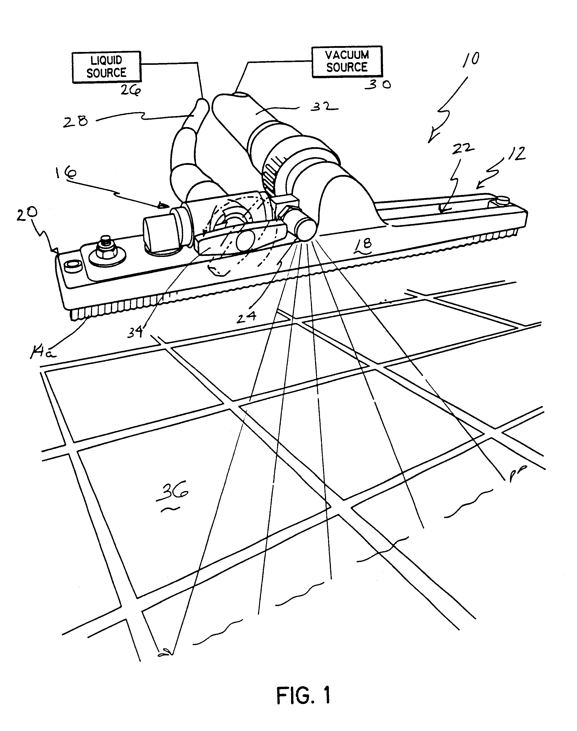
1. Field of the InventionThis invention is directed to a multi-functional floor-cleaning tool capable of directing a high-pressure jet of liquid onto a hard surface, while substantially confining the liquid to the interior space of the tool when the tool is positioned in contact with the particular surface, and when a vacuum is generated, thereby evacuating soils and sprayed liquid from the interior of the tools to a remote location Such tools are appropriate for use in cleaning any suitable surface, with non-limiting examples including tile floors, tile walls, and other hard surfaces.2. Description of the Related ArtMaintaining the cleanliness of commercial, industrial, institutional, and public buildings is an ongoing effort, and at times, an effort which seems more like a losing battle. This is particularly true for areas such as restrooms, locker rooms, cafeterias, food service kitchens, patient rooms, waiting rooms, factory floors, and other high-traffic areas, where the volume...
Claims
Login to View More Application Information
Patent Timeline
 IPC IPC(8): A47L11/00A47L11/03A47L9/02A47L11/34B08B3/02E01H1/10E01H1/00
CPCA47L9/02A47L11/03A47L11/34E01H1/103B08B3/024A47L11/4088B08B2203/0229
InventorROBINSON, ROBERT S.
OwnerKAIVAC