Method for correcting optical proximity effects in a lithographic process using the radius of curvature of shapes on a mask

a technology of optical proximity and lithographic process, which is applied in the direction of photomechanical equipment, instruments, originals for photomechanical treatment, etc., can solve the problems of reducing on the verge of reaching the limits of the lithographic process capacity, and imposing highly unpredictable effects, so as to reduce the sharpness of images and minimize any distortion

Inactive Publication Date: 2003-11-18
GOOGLE LLC
View PDF1 Cites 46 Cited by
  • Summary
  • Abstract
  • Description
  • Claims
  • Application Information

AI Technical Summary

Benefits of technology

It is another object to recognize that optical proximity effects are low-pass filter in nature and to take full advantage of this recognition by better controlling the critical dimensions of the shapes on a mask.
As previously described, a primary aspect of the present invention relates to the optical proximity effects acting as a low pass filter and stemming from the fact that it is not possible to print images having a high frequency content. It becomes then advantageous to create images on a mask that are totally devoid of high frequency components. Using the inventive Optical Proximity Correction Method (OPC), image ends are distorted in a way that makes them devoid of any high frequency components which cannot be printed on the wafer. This is realized by replacing (or distorting) shapes having a high spatial frequency content by shapes with low spatial frequency content. Thus, it becomes necessary to first identify the presence of sharp corners in the shapes having high frequency components. Then, the sharp corners are replaced by smoother curves having a smaller radius of curvature, i.e., with only low-frequency components. Finally, keeping in mind that lithographic masks containing curved shapes are currently difficult to manufacture and inspect, each curved contour of the shape is approximated by another having Ortho (i.e., parallel to either the x or y axis) or Ortho-45 (i.e., parallel to 45 or 135 degree lines) orientation. The resultant Ortho or Ortho-45 shapes closely follow the contour of the curved shapes, minimizing any distortions and making the manufacturing of the curved shapes on the mask feasible. Three steps in the procedure achieve this objective:

Problems solved by technology

The advent of advanced lithographic techniques and the attempt of chip manufacturers to closely follow Moore's law predicting an exponential growth of number of components on a chip and their shrinkage on the wafer is making the process of designing tools for automating the chip design extremely challenging.
As the components on the chip become smaller, they are now on the verge of reaching the limits of capacity of the lithographic process.
The non-linearities associated with this lithographic process of imprinting and the laws of physics associated with light (including diffraction of light waves) makes impressing highly unpredictable.
In addition to the non-linearity associated with the optical effects, the process of developing after exposing the wafer and the photo-resist thereon also adds to the uncertainty associated with the critical dimensions of the features.
Since at this stage the size of the features is still large compared to the wavelength of the light used in the lithographic process, the optical proximity does not contribute significantly to the total error budget of the chip manufacturing.
However, as the size of the features continuously shrinks, mask designers have continuously readapted earlier techniques to obtain the desired results.

Method used


Image

  • Method for correcting optical proximity effects in a lithographic process using the radius of curvature of shapes on a mask
  • Method for correcting optical proximity effects in a lithographic process using the radius of curvature of shapes on a mask
  • Method for correcting optical proximity effects in a lithographic process using the radius of curvature of shapes on a mask

Examples


example 2

Shown in FIGS. 8.1 and 8.2 are, respectively, a shape in the form of an L-shaped bracket and the simulated shape. This shape is used to measure the radius of curvature at points R1, R2, R3, R4, R5 and R6 (FIG. 8.2). The output curve is depicted after using any conventional method for generating a Bezier curve (FIG. 8.3). However, as previously stated, this shape is not easily manufacturable. Accordingly, a new shape is created having only Ortho-45 sides (FIG. 8.4).

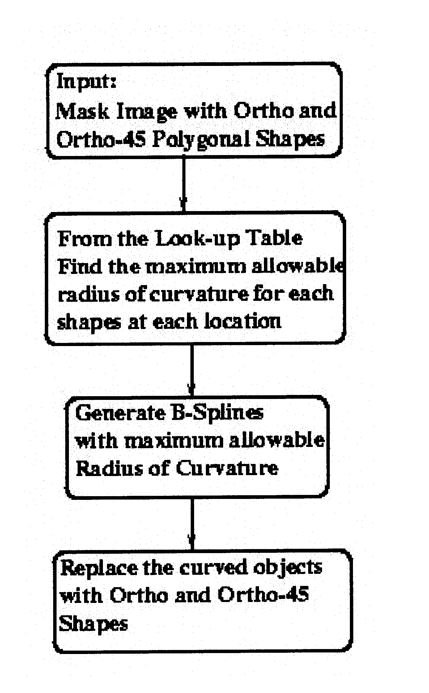
The last two stages comprising the optical proximity correction are further described in the flow chart shown in FIG. 9 which includes generating a mask with limited radius of curvature and approximating smooth curves with Ortho and Ortho-45 sides.

Hereinafter is described a step by step description of the algorithm. Note that an input to this flowchart is the actual layout of the designed mask used in conjunction with the table of maximum radius of curvature described with reference to flowchart of FIG. 4. The output of th...


PUM

PropertyMeasurementUnit
radius of curvatureaaaaaaaaaa
radii of curvatureaaaaaaaaaa
curved shapesaaaaaaaaaa

Abstract

A method for correcting proximity effects on a mask used in a lithographic process is described. Proximity effects are recognized to be low-pass filter in nature and full advantage of this fact is taken. Shapes having a high radius of curvature are replaced with mask patterns having smaller radii of curvature, rendering the image less susceptible to low-pass filtering effects while achieving a high fidelity printing on the mask. This approach provides better control to the mask designer to handle critical dimensions of the shapes on the mask. The method for correcting proximity effects on a mask includes the steps of providing at least one curved shape to approximate the contour of a polygon on the mask, the polygon controlling the contour of the a least one curved shape; defining the curved shape by way of a plurality of radii of curvature; assigning to each side of the polygon one of the radii of curvature; modifying the radius of curvature at each of the sides of the polygon until each of the radii of curvature reaches the maximum allowable limit for that side, the maximum allowable limit being determined from stored values of radii of curvature corresponding to a plurality of predetermined curved shapes; and combining respective curved shapes assigned to adjacent polygon sides to form a resultant closed curved shape.

Description

This invention is generally related to a lithographic process, and more particularly to a method for correcting optical proximity effects using the radius of curvature of shapes imprinted on a mask.The advent of advanced lithographic techniques and the attempt of chip manufacturers to closely follow Moore's law predicting an exponential growth of number of components on a chip and their shrinkage on the wafer is making the process of designing tools for automating the chip design extremely challenging. The chip is imprinted by means of optical lithographic techniques on the silicon wafer by way of chrome on glass masks. As the components on the chip become smaller, they are now on the verge of reaching the limits of capacity of the lithographic process. The non-linearities associated with this lithographic process of imprinting and the laws of physics associated with light (including diffraction of light waves) makes impressing highly unpredictable. For instance, rectangles are fore...

Claims


Application Information

Patent Timeline
Patent Type & Authority Patents(United States)
IPC IPC(8): G03F7/20G03F1/14G03F1/00G03F1/36
CPCG03F1/144G03F7/70441G03F1/36
Inventor MUKHERJEE, MAHARAJ
Owner GOOGLE LLC
Why Eureka
Try Eureka