Dental bar attachment for implants

a technology for dentures and bars, applied in the field of dentures with bars and implants, can solve the problems of wear between clips and bars, and the magnetic assembly embedded in the denture base cannot be used with this type of keeper

Inactive Publication Date: 2003-11-25
AICHI STEEL
View PDF13 Cites 51 Cited by
  • Summary
  • Abstract
  • Description
  • Claims
  • Application Information

AI Technical Summary

Benefits of technology

The present invention of a bar type dental attachment for use with implants comprises a bar shaped keeper which is supported by a fixed base embedded in the jawbone and has at least one section that is an arced attractive surface whose radius of curvature is fixed, and a magnetic assembly comprising: a magnetic body whose magnetic polls face the yoke plates; a pair of yokes which is arranged on both sides of said magnetic body in a sandwich-like fashion, each of which has an attractive face opposite to said attractive face of said keeper, and which fit easily to said attractive face of said keeper; a seal part made of anticorrosive non-magnetic material which hermetically seals at least a part of the lateral face of said magnetic body between said pair of said yoke plates.
The present invention of a bar type dental attachment for implants makes it easy to insert or remove a denture because the denture is fixed to the implants by magnetic attractive force. That is, it is different from prior attachments, which fix dentures elastically by using clips, because it is unnecessary to insert the denture precisely or to press the denture in, and it is possible to insert or remove the denture with a simple motion.
Because the pair of yoke plates of the magnetic assembly of presently invented dental attachment has an attractive face whose shape fits to the arc shaped section of the bar type keeper, the magnetic assembly fits to the keeper well. The present invention also has single-axis rotation and can move corresponding with the seesaw movement of the denture during occlusion. In addition, because the pair of said yoke plates is arranged on both sides of the magnetic body like a sandwich and the magnetic circuit is closed, the magnetic attractive force between the keeper and the magnetic assembly is strong, so the present attachment can sufficiently retain denture.
This seal part, being welded hermetically between a pair of yoke plates, can be a ring-shaped cap that covers the lateral face of the magnetic body. The structure, in which a ring-shaped cap covers the lateral face of a magnetic body and the pair of yoke plates is exposed, enables magnetic body, as is mentioned above, to avoid corrosion while the entire volume of the magnetic assembly is kept small. Therefore, the dental attachment becomes a more suitable size to be used in the mouth.
Furthermore, the magnetic assembly of the present bar type dental attachment for implants can have a convex, or a concave part on the lateral face opposite to said attractive face. With such a concave or convex part, the magnetic assembly can be fixed more firmly to the denture base. Even though the magnetic assembly is embedded in a dental base with adhesive resin, after long use, separation from denture base may occur. By forming said convex or concave part, the magnetic assembly is fixed under a condition wherein said concave part digs into the denture base, or said concave is filled with the denture base. Therefore separation of the magnetic assembly and denture base can be more surely prevented.
And preset invented bar type dental attachment for implants can have a surface treatment on said attractive face to enhance the resistance to wear. By giving a surface treatment to the attractive surface in contact with a keeper, wear on the attractive face of the magnetic assembly during occlusion or over repeated insertion and removal can be diminished and the dental attachment can have a longer life.

Problems solved by technology

But using this clip and bar type dental attachment, one must press the clips made of mental or plastic on to the bar when putting in the denture and denture is not easily inserted.
Furthermore, there is a problem of wear between the clips and the bar.
And the magnetic assembly embedded in denture base cannot be used with this bar type keeper because the contact face of said bar type keeper has a cylindrically shaped lateral face and the two pieces will not fit.

Method used


Image

  • Dental bar attachment for implants
  • Dental bar attachment for implants
  • Dental bar attachment for implants

Examples


Embodiment Construction

The embodiment of present invented bar type dental attachment for implants is explained as follows.

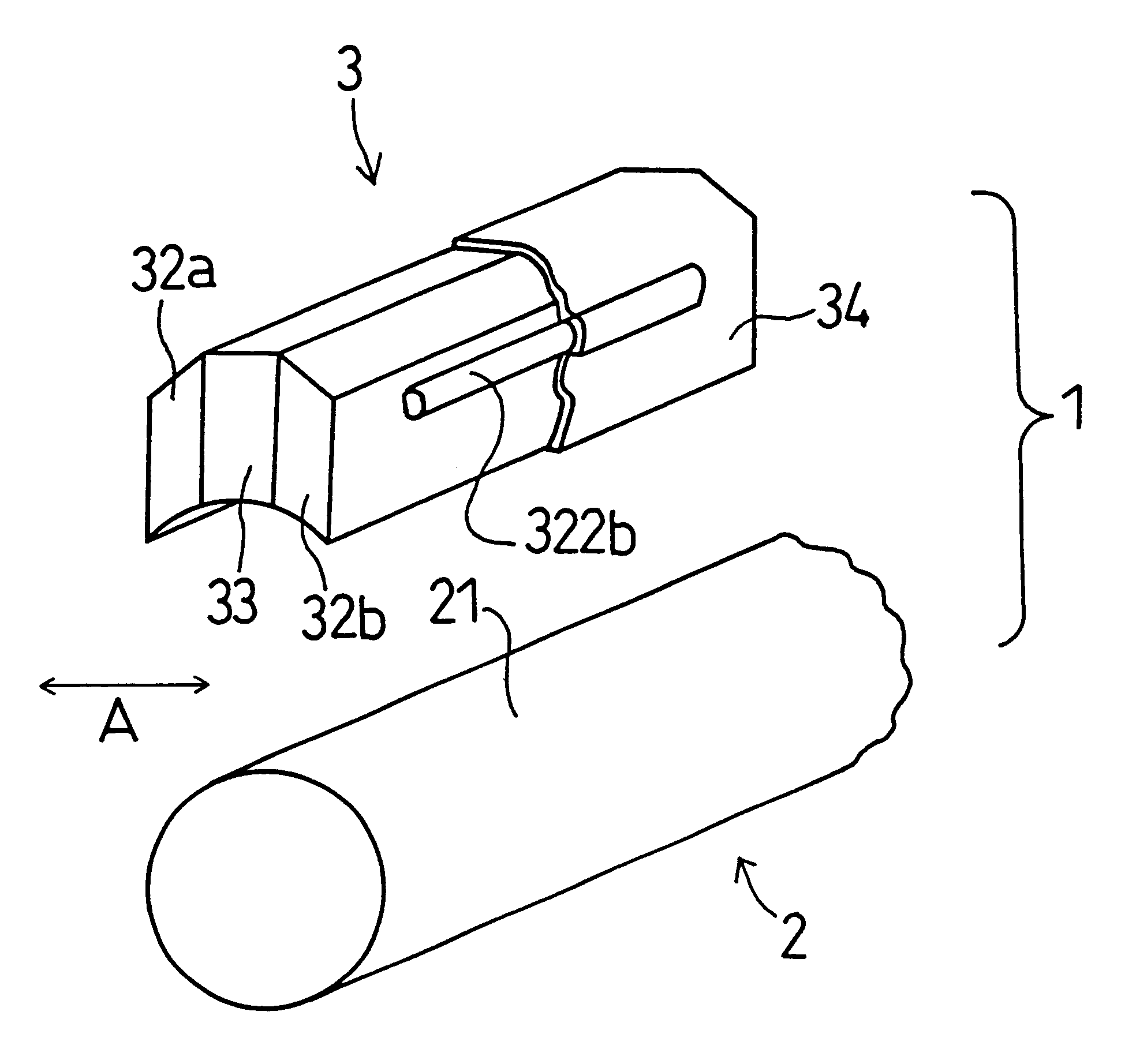
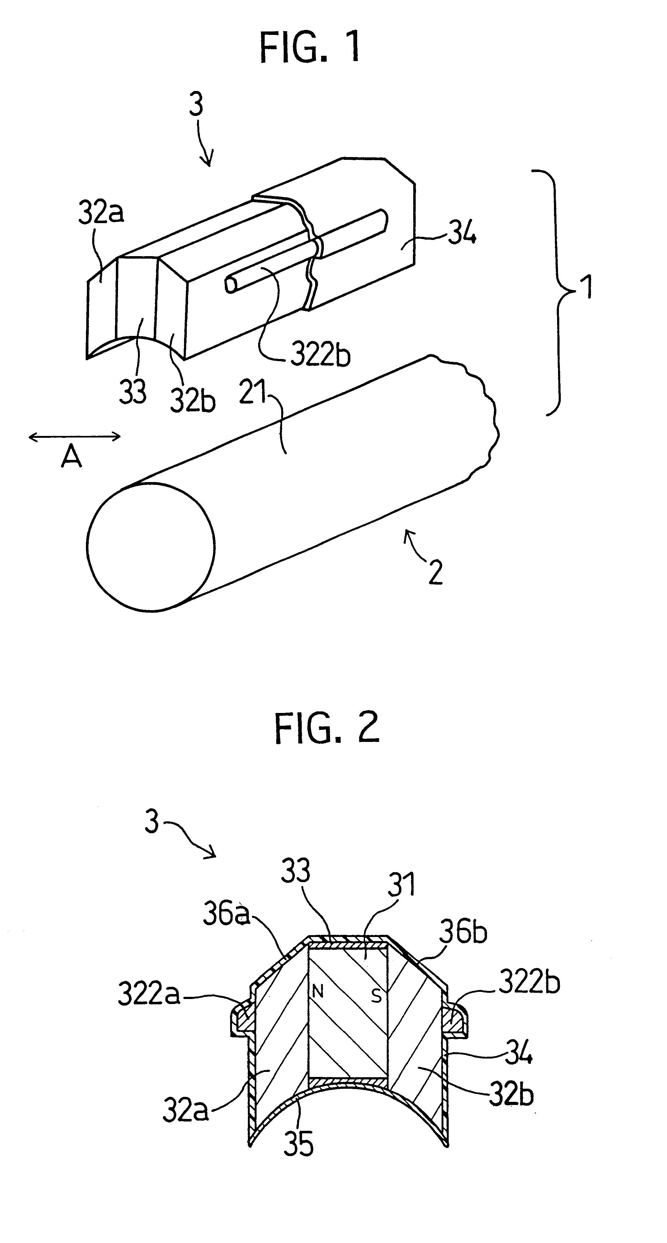
A perspective view of the representative embodiment of the present invention of a bar type dental attachment for implants is shown in FIG. 1 and a magnified vertical section of magnetic assembly composing the dental attachment is shown in FIG. 2.

As is shown in FIG. 1, the dental attachment 1 of present embodiment comprises the cylindrically shaped keeper 2 made of magnetic material and the magnetic assembly 3 attracted by magnetic attractive force to the cylindrically shaped lateral attractive face of keeper 2.

First, the keeper 2 is explained. The keeper 2 has a cylindrical shape and is made of 19Cr--2Mo--0.2Ti. The keeper 2 has a cylindrical shape in the present embodiment, but the shape is not limited to this shape, as long as it is a bar shape and it has at least a part of the attractive face whose arced section has a fixed radius of curvature. For example, a bar shaped keeper with ...


PUM


Abstract

The present invention is a bar type dental attachment for implants that makes use of magnetic attractive force to secure a denture in place. This bar type dental attachment can rotate corresponding to the movement of the denture during occlusion. The present invention has excellent wear resistance and makes insertion and removal of the denture easy. The present invention has a bar type keeper with an arced attractive face with a constant radius of curvature, and a magnetic assembly that comprises a magnet, a pair of yoke plates sandwiching the magnet, and a seal material made of anticorrosive non-magnetic material that covers the magnet and is hermetically sealed. The attractive surface of the magnetic assembly is curved to fit the keeper.

Description

The present invention relates to a bar-type dental attachment that can be used to fix a denture by a magnetic attractive force to the jawbone via dental implants.PRIOR ARTAs shown in FIG. 3 and FIG. 4, in dental treatment there currently exists a bar and clip type dental attachment used to fix a denture to an implant. In this type of attachment, the denture is clipped to a cylindrically shaped bar 41, which is supported by a fixed base embedded in the jawbone, with clips 42 implanted in the denture base. In this attachment, clips fix the denture elastically.But using this clip and bar type dental attachment, one must press the clips made of mental or plastic on to the bar when putting in the denture and denture is not easily inserted. Furthermore, there is a problem of wear between the clips and the bar.On the other hand, as is shown in laid-open Japanese patent number 8-317941, there are have been many attempts to use magnetic attractive force to fix a denture to implants because d...

Claims


Application Information

Patent Timeline
Patent Type & Authority Patents(United States)
IPC IPC(8): A61C13/225A61C13/275A61C13/235A61C8/00
CPCA61C8/0048A61C13/275A61C13/235A61C8/00
Inventor HONKURA, YOSHINOBUARAI, KAZUO
Owner AICHI STEEL
Why Eureka
Try Eureka