
Foam-filled antenna and method of manufacturing same

a technology of foam-filled antennas and antennas, which is applied in the direction of antennas, basic electric elements, electrical appliances, etc., can solve the problems of prone to performance degradation, difficult and expensive manufacture of antennas, and degrade transmission performance, and achieve the effect of accurate shape retention

Inactive Publication Date: 2003-12-16
H & O IND PROPERTIES L L C
View PDF14 Cites 26 Cited by
  • Summary
  • Abstract
  • Description
  • Claims
  • Application Information

AI Technical Summary

Benefits of technology

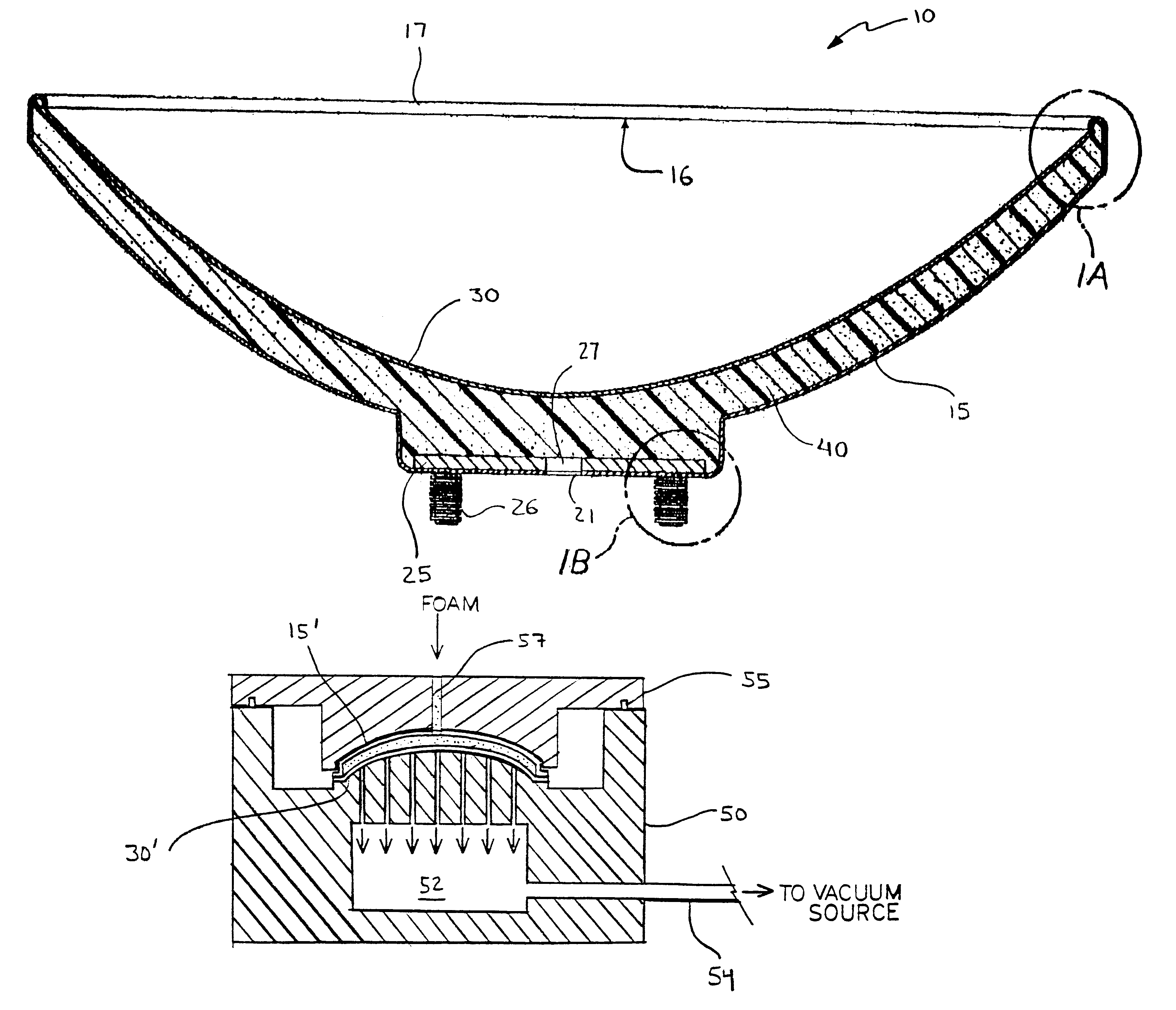
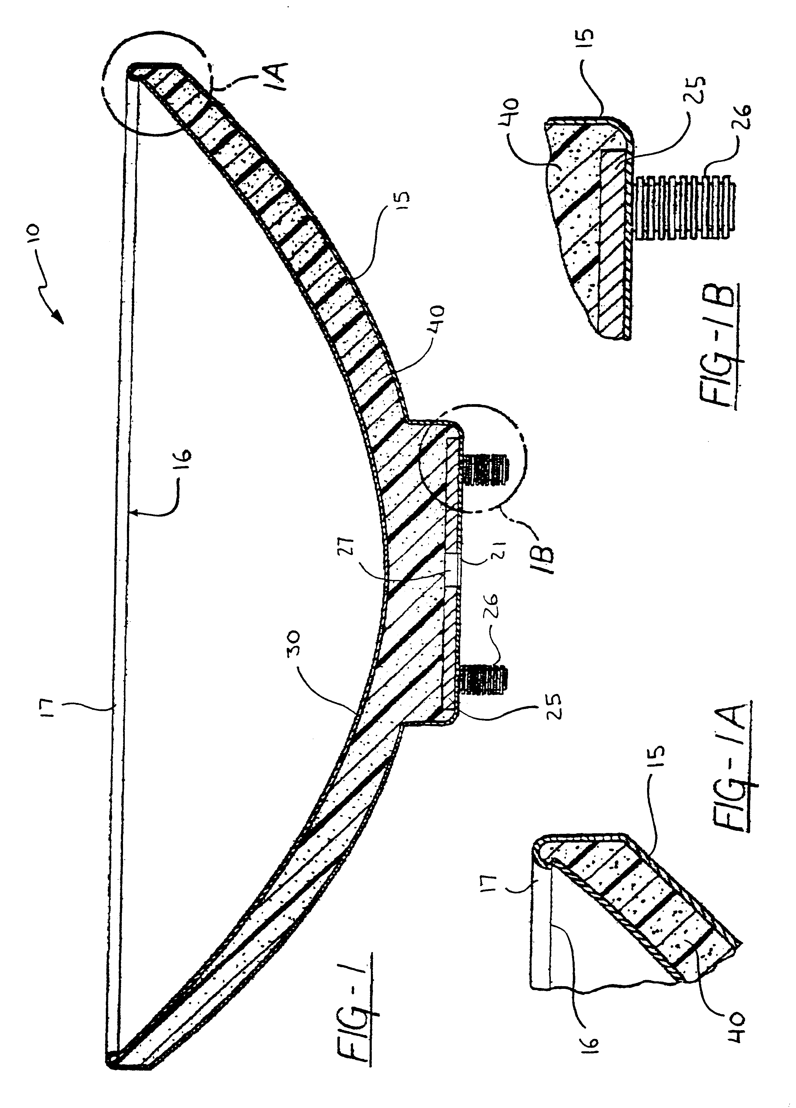
The present invention addresses and solves the problems discussed above, and encompasses other features and advantages, by providing a parabolic, or dish-type, antenna comprising a backing section and a reflector of deformable material, such as polymer, metal, alloy, etc., the backing section and reflector being mated to define a hollow interior cavity that is filled with a rigid support structure comprising a closed-cell foam. Advantageously, the rigid support foam provides accurate shape retention for the preferred parabolic curvature of the antenna reflector, even through variations in temperature, wind loading, and other environmental influences.

Problems solved by technology

While parabolic antennas are relatively simple in their design, the fact that signal reception and transmission is dependent upon the shape of the reflector face, or "dish", renders their precise manufacture difficult and, sometimes, expensive.
The importance of dish tolerances is especially pronounced in transmission antennas, where variations in the surface of the dish too far from a desired curvature will significantly degrade transmission performance.
These drawbacks make such antennas prone to performance degradation, and render them particularly ill-suited to use as transmitting antennas.
However, the method of this patent is complicated, requires considerable parts fabrication relative to the structural means, and so is not suited to the inexpensive mass-production of antenna.

Method used


Image

  • Foam-filled antenna and method of manufacturing same
  • Foam-filled antenna and method of manufacturing same
  • Foam-filled antenna and method of manufacturing same

Examples


Embodiment Construction

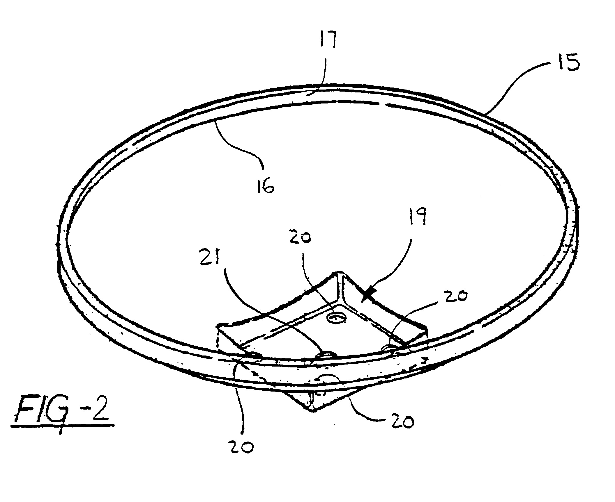
Referring now to the drawings, wherein like numerals indicate like or corresponding parts, the present inventive apparatus will be seen to generally comprise a parabolic antenna comprising at least a reflector of deformable material, the reflector having a parabolic shape of predetermined close tolerances, and a rigid structural substrate provided on one side of and coextensive with the reflector, the rigid structural substrate comprising a closed-cell foam sufficient to accurately maintain the close tolerances of the reflector's parabolic shape.

According to a first embodiment of this invention, shown in FIG. 1, the antenna 10 preferably includes a backing section 15 and a reflector 30, the backing section and reflector being mateable to define a hollow interior cavity filled with a closed-cell foam 40 forming a rigid support structure for maintaining the close tolerances of the reflector against distortion. The backing section 15 and reflector 30 comprise components formed of suita...


PUM

PropertyMeasurementUnit
Shapeaaaaaaaaaa

Abstract

A parabolic antenna comprising at least a reflector of deformable material, the reflector having a parabolic shape of a preferred curvature, and a rigid structural substrate comprising a foam sufficient to maintain the parabolic shape of the reflector against significant deviation from said parabolic shape. The deformable material of the reflector is characterized by its inability to maintain the parabolic shape of a preferred curvature in the absence of the rigid structural substrate. A method of forming the inventive antenna is disclosed, comprising the steps of: Providing a backing section and a reflector made of deformable material, the backing section and reflector being mateable to define a hollow interior cavity; maintaining the reflector on a forming die in conformance with a preferred curvature of the reflector; and injecting an expandable, foam slurry into the hollow interior cavity and curing the foam slurry to form the antenna.

Description

The present invention relates to parabolic antennas, such as are employed to receive and / or transmit carrier signals, and a method of forming such antennas and other metal or alloy parts where precise tolerances are required in the finished product. More particularly, the present invention relates to a parabolic antenna comprising a backing section and reflector made of deformable material, for instance metal or alloy, the backing section and reflector being mated to define a hollow interior cavity that is filled with a rigid support structure comprising a closed-cell foam. The present invention also particularly relates to a method of forming accurately dimensioned parts having close tolerances, such as transmission antennas, wherein a deformable material skin, for instance an antenna reflector of metal, is maintained in exact conformance with a vacuum buck, the vacuum buck having a configuration corresponding to the close tolerances of the preferred configuration of the completed ...

Claims


Application Information

Patent Timeline
IPC IPC(8): H01Q15/14
CPCH01Q15/142H01Q15/144Y10T29/49016
Inventor OLINYK, MARKHOMANN, HELMUT F.
Owner H & O IND PROPERTIES L L C
Learn More