Mixing enhancement using axial flow

a technology of axial flow and enhancement, applied in the field of mixing enhancement, can solve the problems of reduced efficiency, difficult to complete mixing, and excessive production of pollutants

Inactive Publication Date: 2003-12-23
RGT UNIV OF CALIFORNIA
View PDF16 Cites 16 Cited by
  • Summary
  • Abstract
  • Description
  • Claims
  • Application Information

AI Technical Summary

Problems solved by technology

Otherwise, combustion is incomplete, leading to reduced efficiency and excessive production of pollutants.
Complete mixing is often difficult because of the limited space and / or time available for the reactants to mix thoroughly.
However, these mechanical mixers decrease the momentum of the flow, thus compromise the penetration of the reactants into the combustion zone.
Furthermore, mechanical mixers cause total pressure losses which in turn cause decreased system efficiency and, in propulsion devices, loss of thrust.
In small-scale combustion applications, such as in a piston cylinder of a diesel engine, mechanical mixers would be very costly to install and maintain because of their complex shapes.
Although lobe mixers can provide adequate mixing, they reduce thrust and increase the weight and complexity of the engine.
The thrust reduction is particularly severe when the engine exhaust is supersonic.
Since the gases enter at supersonic speeds, mixing is very slow.
Enhancing the mixing of gases in this case with installation of a mechanical mixer on each injector is impractical due to the large number of injectors.
Because the dimensions of jet nozzles used in spray depositions are very small, installation of mechanical mixers is impractical.

Method used


Image

  • Mixing enhancement using axial flow
  • Mixing enhancement using axial flow
  • Mixing enhancement using axial flow

Examples


first embodiment

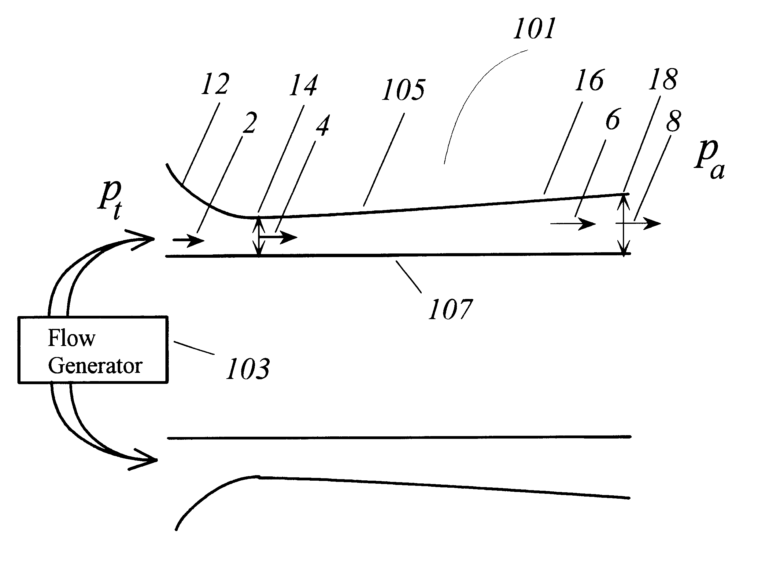
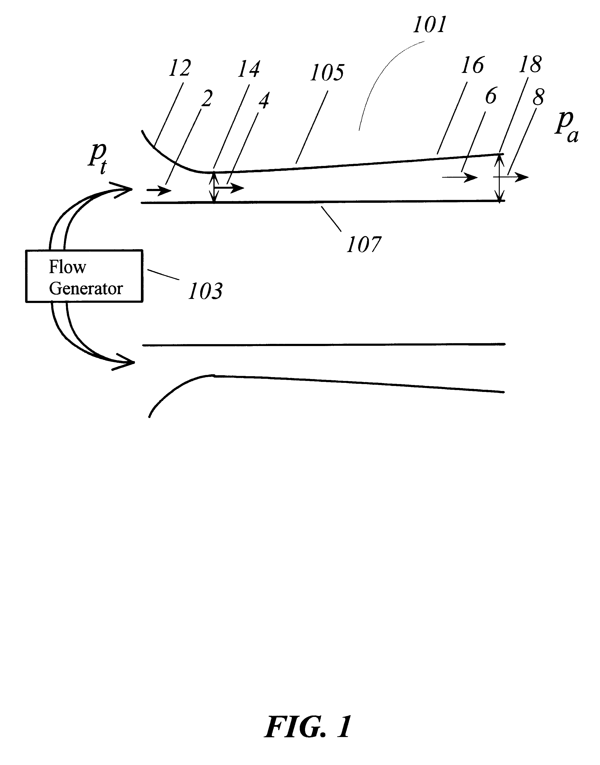
FIG. 1 illustrates the present invention. FIG. 1 shows an exemplary converging-diverging duct 101. From area 12 to area 14, the duct 101 is converging. From area 14 to area 18, the duct 101 is diverging.

The duct 101 comprises an effective outer wall 105, an effective inner wall 107, a cross sectional area A.sub.1 at area 14, and an exit area A.sub.e at area 18. The cross sectional area A.sub.1 and the exit area A.sub.e are different in size.

As shown in FIG. 1, the converging-diverging feature of the duct 101 is caused by the shape of the effective outer wall 105. Equivalently, this feature can also be caused by the shape of the effective inner wall 107, or by both effective walls.

The effective walls 105, 107 can be either rigid or fluid. For example, the effective inner wall can be formed by a centerbody, or by an outer wall of a fluid stream nozzle. In such cases, the effective inner wall is rigid. The effective inner wall can also be formed by a boundary of a fluid stream, in whic...

second embodiment

FIG. 5 illustrates the present invention. FIG. 5 shows a longitudinal sectional view of an exemplary converging-diverging-converging duct 501. From area 23 to area 25, the duct 501 is converging. From area 25 to area 29, the duct 501 is diverging. From area 29 to area 33, the duct 501 is converging.

The duct 501 comprises an effective outer wall 505, an effective inner wall 507, a cross sectional area A.sub.min at area 29, a maximum area A.sub.max at area 29 and an exit area A.sub.e at area 33. The cross sectional area A.sub.min and the exit area A.sub.e are different in size.

As shown in FIG. 5, the converging-diverging-converging feature of the duct 501 is caused by the shape of the effective outer wall 505. Equivalently, this feature can also be caused by the shape of the effective inner wall 507, or by both effective walls.

The effective walls 505, 507 can be either rigid or fluid. For example, the effective inner wall 507 can be formed by a centerbody, or by an outer wall of a jet...

third embodiment

FIG. 8 is the present invention, which comprises a duct 801, a flow generator 103, and a centerbody 809. From area 812 to area 816, the duct 801 is converging. From area 816 to area 820, the duct 801 is shown as constant for illustrative purposes only, it can also be diverging. From area 820 to 826, the duct 801 is diverging.

Referring to FIG. 8, the duct 801 comprises an effective outer wall 805, an effective inner wall 807, a cross sectional area A.sub.min at area 816, and an exit area A.sub.e at area 826. The cross sectional area A.sub.min is smaller than the exit area A.sub.e. The effective inner wall 807 is formed by the centerbody 809. Since the centerbody 809 extends past the exit area 828, the effective inner wall 807 is longer than the effective outer wall 805. The present invention does not require that the centerbody be extended past the exit area. The endpoint 830 of the centerbody 809 can also be coplanar with the duct exit area 826, or recessed from the termination of t...


PUM


Abstract

A method and an apparatus for enhancing fluid mixing. The method comprises the following: (a) configuring a duct to have an effective outer wall, an effective inner wall, a cross-sectional shape, a first cross-sectional area and an exit area, the first cross-sectional area and the exit area being different in size; (b) generating a first flow at the first cross-sectional area, the first flow having a total pressure and a speed equal to or greater than a local speed of sound; and (c) generating a positive streamwise pressure gradient in a second flow in proximity of the exit area. The second flow results from the first flow. Fluid mixing is enhanced downstream from the duct exit area.

Description

1. Field of the InventionThe present invention relates generally to mixing enhancement between two or more fluids, at least one of the fluids being a gas supplied under pressure. More particularly, it relates to mixing enhancement in fuel injectors, sprays, chemical lasers, inside the exhaust duct of turbine engines, outside the exhaust duct of jet engines, and other related applications.2. Description of Related ArtMixing enhancement is desirable in a large variety of processes and devices, including combustion, propulsion, fluid pumping, chemical lasers, materials processing, and spray coating.In every combustion system, fuel and oxidizer must be mixed thoroughly and in the correct proportion before reaction takes place. Otherwise, combustion is incomplete, leading to reduced efficiency and excessive production of pollutants. Complete mixing is often difficult because of the limited space and / or time available for the reactants to mix thoroughly. This difficulty is augmented in ca...

Claims


Application Information

Patent Timeline
Patent Type & Authority Patents(United States)
IPC IPC(8): F02K1/46F02K1/36F02K1/00F02K1/38F23D14/22F23D14/00F23R3/28
CPCF02K1/36F02K1/38F02K1/46F23R3/28F23D14/22F05D2260/601Y02T50/671Y02T50/60
Inventor PAPAMOSCHOU, DIMITRI
Owner RGT UNIV OF CALIFORNIA
Why Eureka
Try Eureka