Spare area management method of optical recording medium

a technology of optical recording medium and separate area management, which is applied in the field of optical recording medium, can solve the problems of optical disc loss, defective areas of rewritable optical disc, and inability to perform linear replacement or slippag

Inactive Publication Date: 2003-12-30
LG ELECTRONICS INC
View PDF5 Cites 13 Cited by
  • Summary
  • Abstract
  • Description
  • Claims
  • Application Information

AI Technical Summary

Benefits of technology

An object of the invention is to provide a spare area management method of an optical recording medium which can indicate whether a primary spare area is full and whether a supplementary spare area has been assigned.
Another object of the invention is to provide a spare area management method of an optical recording medium which can indicate whether the spare area is available for a linear replacement.

Problems solved by technology

Thus, the optical discs lose its characteristics and generate an error during recording / playback.
This degradation appears as a defect area at the time of formatting, recording on or playing back from an optical storage medium.
Also, defective areas of a rewritable optical disc may be caused by a scratch on its surface, particles of dirt and dust, or errors during manufacture.
However, if the spare full flags in all zones have been set, i.e. there is no more spare area, a slipping or linear replacement cannot be executed.
Moreover, when defective sectors are registered in the PDL according to the initial formatting or reformatting of the optical disc, data cannot be recorded in those defective sectors, reducing the recording capacity.

Method used


Image

  • Spare area management method of optical recording medium
  • Spare area management method of optical recording medium
  • Spare area management method of optical recording medium

Examples


Embodiment Construction

Reference will now be made in detail to the preferred embodiments of the present invention, examples of which are illustrated in the accompanying drawings.

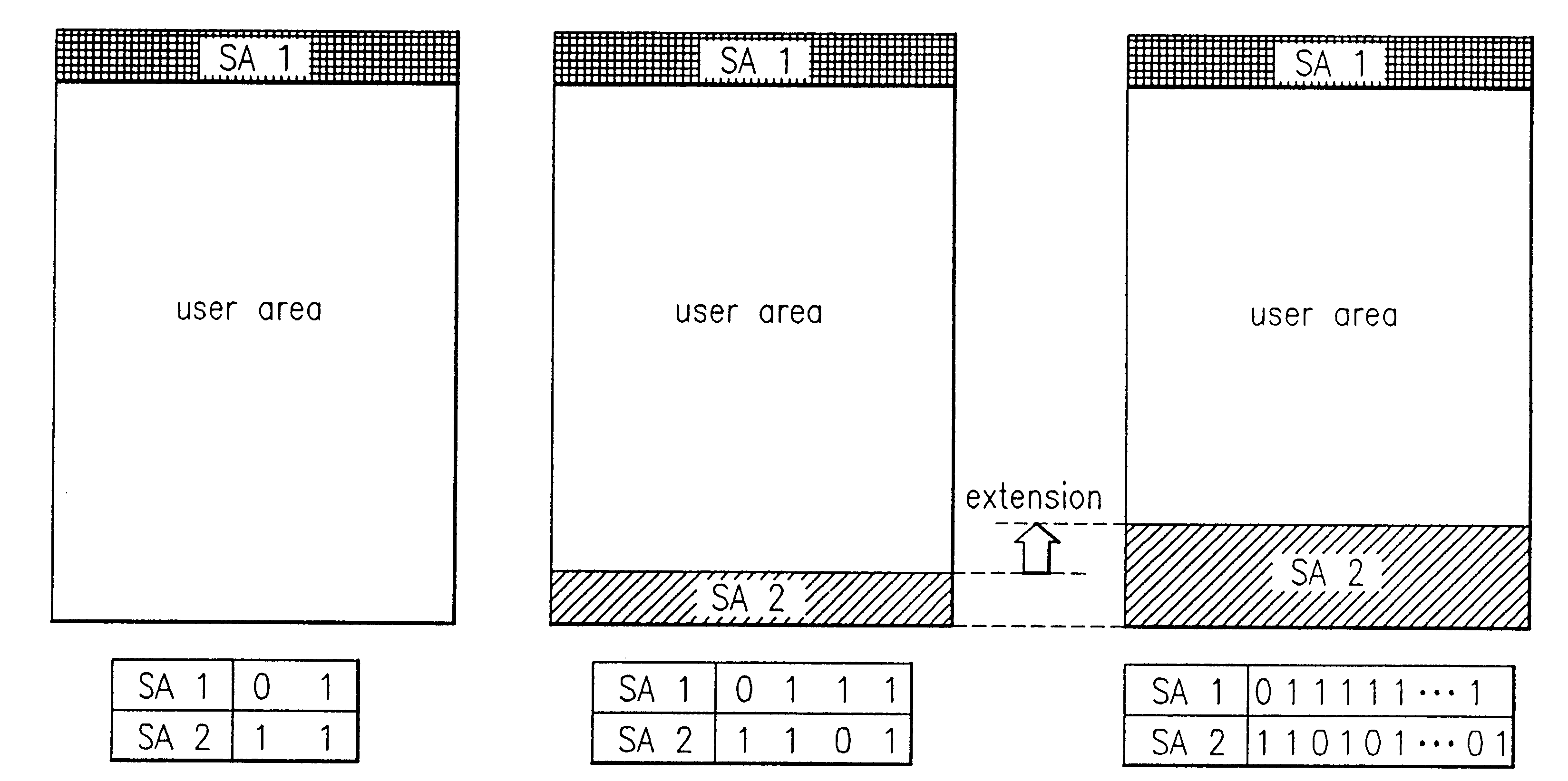
The present invention is generally directed to a spare area management method of an optical recording medium which can indicate by means of identification information whether a primary spare area assigned on the top portion of data area is full or a supplementary spare area assigned on the bottom portion of the data area is available.

The identification information is recorded independently from the primary and supplementary spare areas. In the present invention, for the convenience of an explanation, the identification information for indicating whether the primary spare area is full will be called `a primary spare area full flag` and the identification information for indicating whether the supplementary spare area is assigned or available will be called `a supplementary spare area full flag`.

FIG. 5 shows a data structure where t...


PUM

PropertyMeasurementUnit
data areaaaaaaaaaaa
spare areasaaaaaaaaaa
spare areaaaaaaaaaaa

Abstract

A recording medium and a spare area management method for an optical recording medium are provided. The spare area management method utilizes an identification information to indicate whether a primary spare area is full or a supplementary spare area has been assigned or extended, as necessary. The spare area management method improves the performance of the driver by replacing a defective block with a spare block nearer to the defective block.

Description

BACKGROUND OF THE INVENTION1. Field of the InventionThe present invention relates to an optical recording medium and more particularly, to a spare area management method of a rewritable optical recording medium.2. Discussion of Related ArtAn optical storage medium is generally divided into a read only memory (ROM), a write once read many (WORM) memory into which data can be written one time, and rewritable memories into which data can be written several times. Rewritable optical storage mediums, i.e. optical discs, include rewritable compact discs (CD-RW) and rewritable digital versatile discs (DVD-RW, DVD-RAM, DVD+RW).The operations of writing and playing back data in a rewritable optical disc may be repeated. This repeated process alters the ratio of storage layers for recording data into the optical disc from the initial ratio. Thus, the optical discs lose its characteristics and generate an error during recording / playback. This degradation appears as a defect area at the time of...

Claims


Application Information

Patent Timeline
Patent Type & Authority Patents(United States)
IPC IPC(8): G06F12/00G11B5/09G11B7/004G11B7/0055G11B7/007G11B20/10G11B20/12G11B20/18
CPCG11B20/1217G11B20/1883G11B2220/2575G11B2220/20G11B20/12
Inventor PARK, YONG CHEOLHAN, YONG HEE
Owner LG ELECTRONICS INC
Why Eureka
Try Eureka