Connector

a technology of connecting rods and connecting rods, applied in the direction of coupling contact members, coupling device connections, coupling protective earth/shielding arrangements, etc., can solve the problems of small torsional twist of two beams, inability to expect the contribution of contact pressure, damage to female contacts,

Inactive Publication Date: 2004-01-06
FCI AMERICAS TECH INC (US)
View PDF13 Cites 141 Cited by
  • Summary
  • Abstract
  • Description
  • Claims
  • Application Information

AI Technical Summary

Problems solved by technology

In addition, when the angle of the width direction of the male contact with respect to the direction of separation of the pair of beams is larger than 60.degree., the amount of torsional twist of the two beams becomes small, and a contribution to the contact pressure cannot be expected.
In this connector, the contact state between the female and male contact is attained by engaging one housing that anchors the male contacts and the other housing that anchors the female contacts, but if both housings are not correctly aligned when they are engaged, the edge of one housing is caught in the interior space of the other housing, and the female contacts will be damaged and deformed.
In this situation, even if the housings are engaged with each other, a state of contact between the female and male contacts cannot be attained.

Method used


Image

  • Connector
  • Connector
  • Connector

Examples


first embodiment

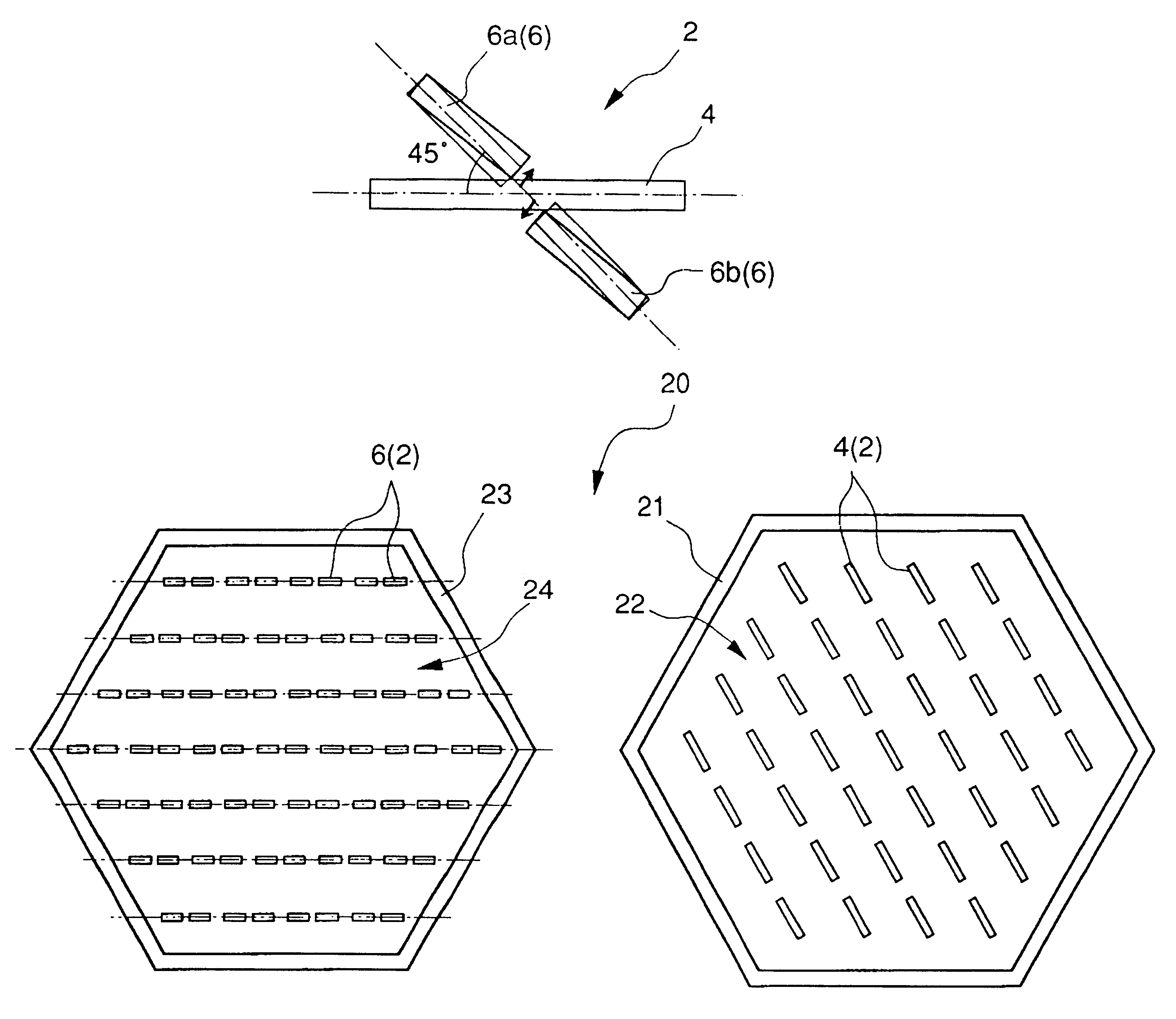
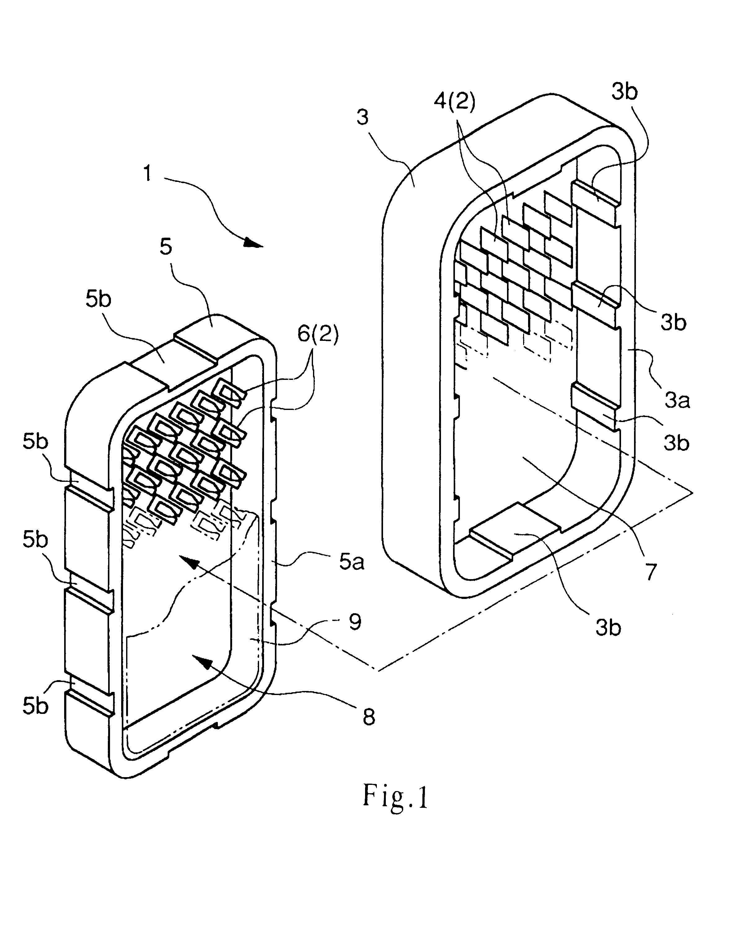
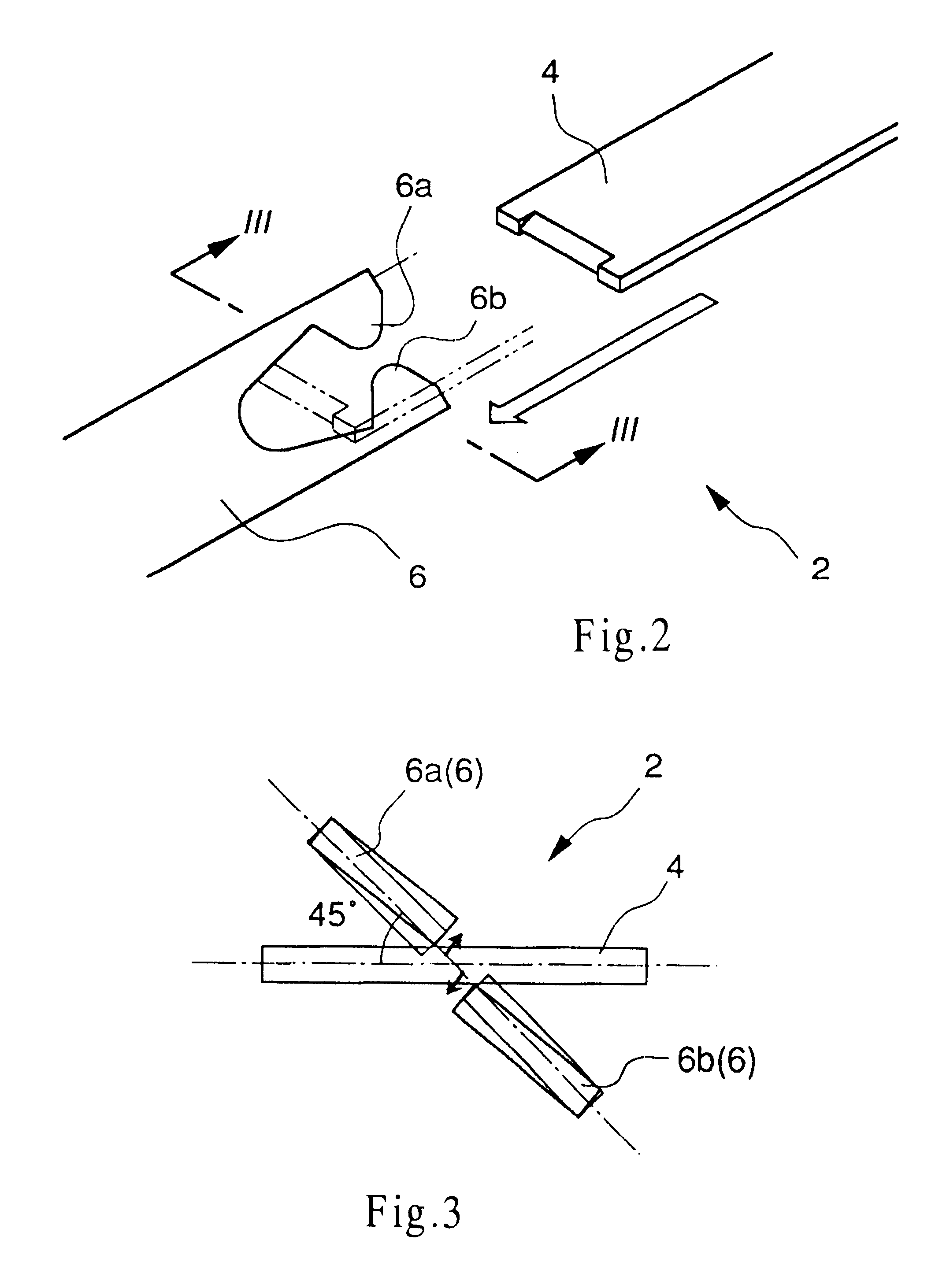
the connector according to the present invention will be explained referring to FIG. 1 through FIG. 4. The connector 1 shown in FIG. 1 has a first connector 1A that provides plurality of tuning fork-type contacts 2, and on which male contacts 4 are attached and arranged horizontally and vertically on one housing 3, and a second connector 1B on which the female contacts 6 are attached and arranged on the other housings so as to conform to the arrangement of the male contacts 4.

The housing 3 is rectangular when viewed in planar perspective, and on the perimeter edge, a mating area is defined by forming a wall 3a along the entire perimeter, and the part on which the male contacts 4 are attached forms a recess 7 (an interior space). The housing 5 is similarly rectangular, and on the perimeter edge, a mating area is defined by forming a wall 5a along the entire perimeter, and the part on which the female contacts 6 are attached forms a recess 8 (an interior space). Both housings 3 and 5 ...


PUM


Abstract

A suitable contact state is attained by an always stable contact pressure between a male contact and a female contact which form a tuning fork type contact. For a contacts providing a tuning fork type contact 2 that attains a contact state by inserting a male contact 4 between a pair of beams 6a and 6b provided on a female contact 6, in the connected state, male contact 4 and female contact 6 are arranged so as to maintain a state wherein the width direction of the male contact is angled relative to the direction of separation of the beams 6a and 6b.

Description

The present invention relates to a connector that uses what is termed a tuning fork-type contact.DESCRIPTION OF THE RELATED ARTOne type of contact provided in connectors is what is termed a tuning fork-type contact. This tuning fork-type contact comprises a female contact with a pair of beams shaped like a tuning fork for connecting with a planar male contact. A state of contact is attained by the beams effecting a restoring force with respect to the male contact that has been inserted between the pair of beams of the female contact.In the conventional tuning fork-type contact described above, because the contact pressure of the female contact is applied only by the elastic deformation of the pair of beams in the direction of separation, the contact pressure changes when there is even a minute change in the distance between the beams.In view of the above circumstances, a need still exists for a connector that provides a tuning fork-type contact that can attain an appropriate contact...

Claims


Application Information

Patent Timeline
Patent Type & Authority Patents(United States)
IPC IPC(8): H01R13/115H01R13/11H01R13/22H01R13/64H01R13/658H01R24/00H01R24/60H01R107/00
CPCH01R13/112
Inventor AZUMA, EDDIE A.
Owner FCI AMERICAS TECH INC (US)
Why Eureka
Try Eureka