Seal and rotary assembly using the seal
- Summary
- Abstract
- Description
- Claims
- Application Information
AI Technical Summary
Benefits of technology
Problems solved by technology
Method used
Image

Examples
embodiment 2
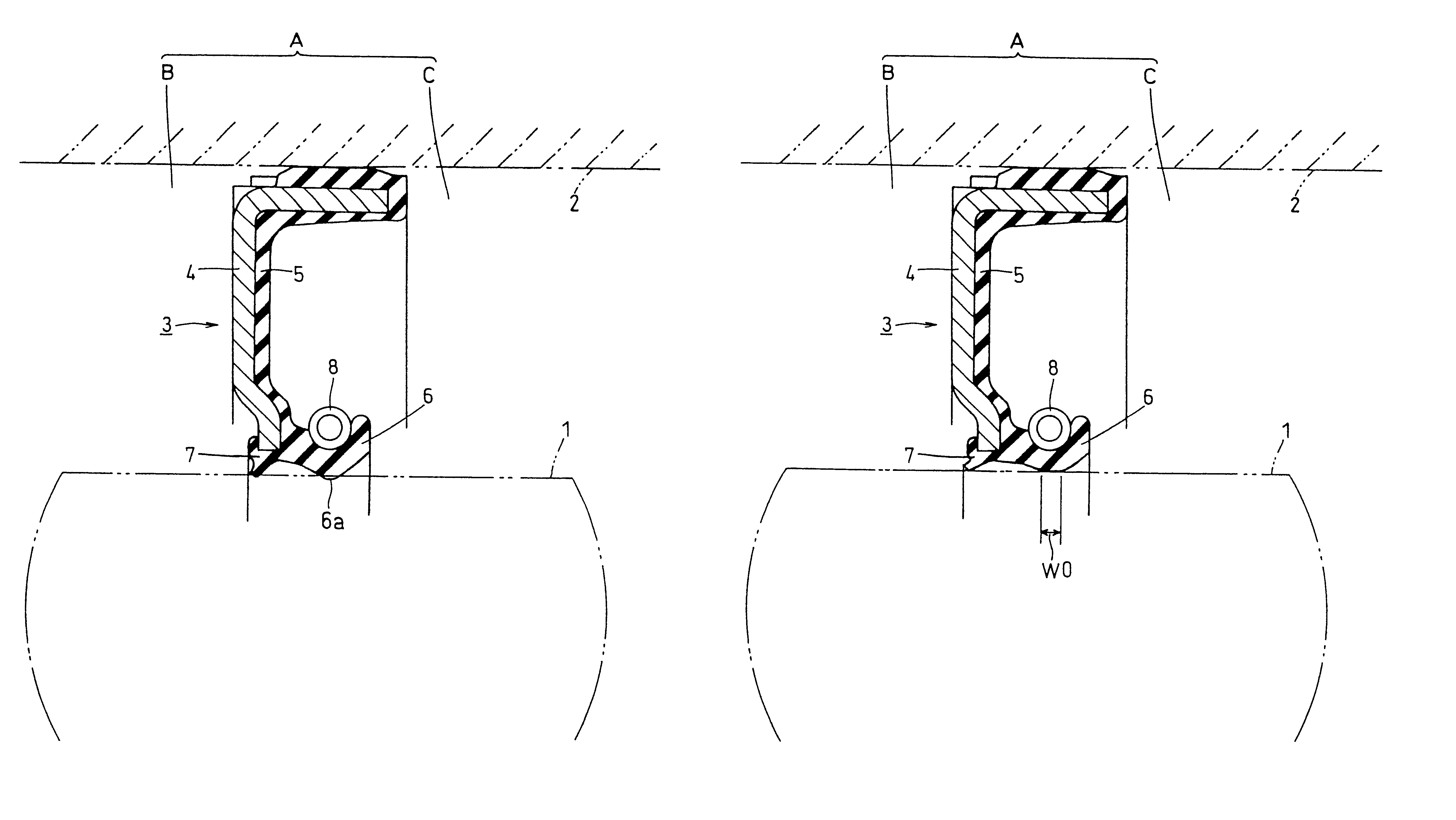
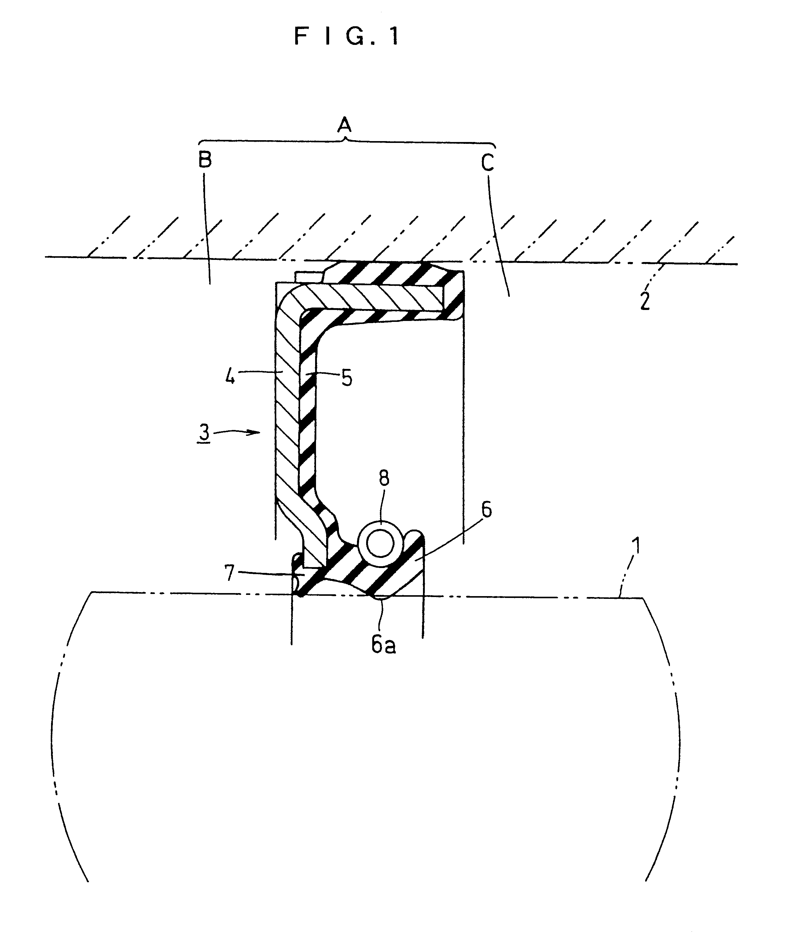
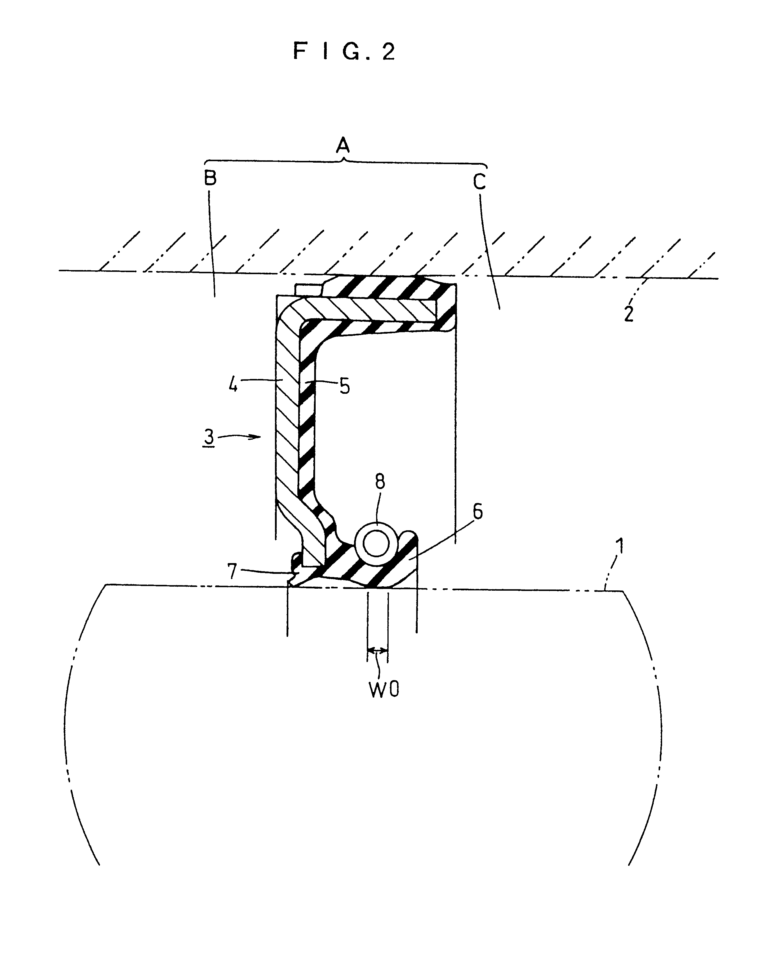
(1) FIG. 3 is a longitudinal sectional view of the upper half of a seal 3 of the present invention in a state before a lip slides on a rotary shaft 1. The longitudinal sectional view of the upper half of the seal 3 in a state in which the lip slides on the rotary shaft 1 is the same as that of FIG. 2 and is not, therefore, shown.
As for the seal 3 in Embodiment 2, the state in which the inside diameter-side vertex portion 6a of a main lip 6 slides on the rotary shaft 1 is not illustrated; however, an axial contact width W0 with respect to the rotary shaft 1 satisfies the relationship represented by the expression (1) and the same function and advantage as those in Embodiment 1 can be obtained.
In Embodiment 2, the seal 3 has a structure in which an annular fluorine-contained resin sheet 9, a metallic annular element 10 and an auxiliary lip 11 separated from an elastic element 5.
The sheet 9 is made of polytetra fluoroethylene (or PTFE such as product name ALP manufactured by STARLITE ...
embodiment 3
(2) FIGS. 4 and 5 relate to Embodiment 3 of the present invention. FIG. 4 is a longitudinal sectional view of the upper half of a seal 3 in a state before a lip slides on a rotary shaft 1. FIG. 5 is a longitudinal sectional view of the upper half of the seal 3 in a state in which the lip slides on the rotary shaft 1.
embodiment 1
In Embodiment 1 shown in FIGS. 1 and 2 and Embodiment 2 shown in FIG. 3, the inside diameter-side vertex portion 6a of the main lip 6 has a round shape in cross section to satisfy the expression (1).
In Embodiment 3, by contrast, the sectional shape of the upper half of a main lip 6 is generally triangle directed toward the rotary shaft 1 side, having a gradually reduced axial contact width and bent from the root side to the inside diameter side. As a result, the slant face 6b of the main lip 6 on the sealing target space B side comes in contact with the rotary shaft 1. Due to this, the main lip 6 satisfies the relationship of slant angle .alpha..sub.b <<slant angle .alpha..sub.c if comparing the slant angle .alpha..sub.b with respect to the axial direction of the sealing target space B-side slant face 6b of the main lip 6 to the slant angle .alpha..sub.c with respect to the axial direction of the atmospheric pressure space C-side slant 6c in the state of FIG. 4. In this case, the in...
PUM
 Abstract
Description
Claims
Application Information
 - Generate Ideas
- Intellectual Property
- Life Sciences
- Materials
- Tech Scout
- Unparalleled Data Quality
- Higher Quality Content
- 60% Fewer Hallucinations
Browse by: Latest US Patents, China's latest patents, Technical Efficacy Thesaurus, Application Domain, Technology Topic, Popular Technical Reports.
© 2025 PatSnap. All rights reserved.Legal|Privacy policy|Modern Slavery Act Transparency Statement|Sitemap|About US| Contact US: help@patsnap.com