Method and apparatus for implementing precision time delays

a time delay and precision technology, applied in pulse generators, pulse manipulation, pulse techniques, etc., can solve the problems of time delays, undesirable non-uniform increments between steps, and the need to move 16 bits from the cmos devi

Inactive Publication Date: 2004-01-13
TDC ACQUISITION HLDG
View PDF10 Cites 118 Cited by
  • Summary
  • Abstract
  • Description
  • Claims
  • Application Information

AI Technical Summary

Problems solved by technology

To the extent that either the ramp deviates from perfect linearity or the threshold step sizes deviate from perfectly uniform steps, then the resulting time delays will include undesirable non-uniform increments between steps.
The resulting dilemma is that it is necessary to move 16 bits from the CMOS device to the SiGe device.

Method used


Image

  • Method and apparatus for implementing precision time delays
  • Method and apparatus for implementing precision time delays
  • Method and apparatus for implementing precision time delays

Examples


Embodiment Construction

The present invention will now be described more fully in detail with reference to the accompanying drawings, in which the preferred embodiments of the invention are shown. This invention should not, however, be construed as limited to the embodiments set forth herein; rather, they are provided so that this disclosure will be thorough and complete and will fully convey the scope of the invention to those skilled in art. Like numbers refer to like elements throughout.

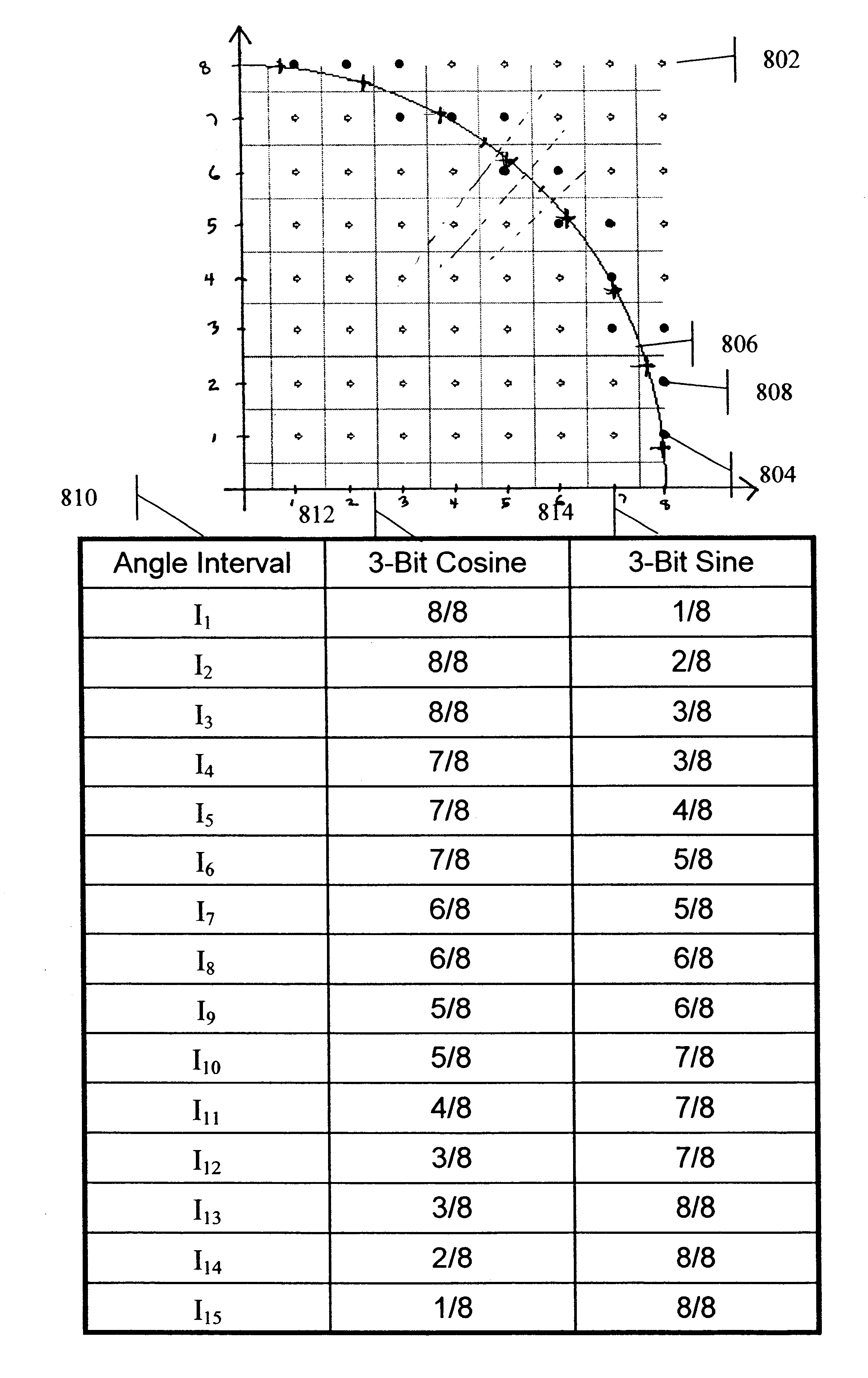
The present invention relates to electronic devices, which include in their functionality, precisely controlled time delays between events or signals. Specifically, this invention enables digitally controlled time delays, with a step size smaller than the delay of a logic gate for the electronic technology being used. Most particularly, the invention provides an optimum strategy for the implementation of time delays, which are achieved by a combination of digitally controlled phase and amplitude processing of an input si...


PUM


Abstract

A system and method of implementing precision time delays that provides important and novel improvements over prior techniques of implementing time delays by utilizing a new strategy for selecting the values in the sine and cosine lookup tables. Sine and cosine values which result in non-uniform amplitudes enable increased overall accuracy with fewer bits communicated from the look-up tables to the analogue portion of the system. Further, herein is provided the addition of a variable amplitude threshold crossing capability following the combining of the sine and cosine signals. The time delay accuracy of the resulting phase and amplitude hybrid system can be improved either by increasing the number of bits in the sine / cosine phase management section or by increasing the number of bits in the amplitude section. There is provided herein an optimum strategy for choosing the number of bits used in the phase and amplitude sections for the best overall delay accuracy with the fewest overall control bits.

Description

1. Field of the InventionThe present invention generally relates to the implementation of time delays, and more specifically, to a system and a method of implementing high precision time delays that can be utilized in an impulse radio system for significant system improvements.2. Background of the Invention and Related ArtIt is very common for electronic systems to require digitally controlled variable time delays between signals. If the desired delay can be achieved with a smallest step size as big as a clock in a synchronous system, then a counter and a comparator can provide the desired delay. The previous methodologies and structure to accomplish this are illustrated in FIG. 1 wherein clock 10 and reset 35 are inputs to counter 15. The output of counter 15 is input to digital compare 25 which has delay count 30 as prior input, thus enabling delay out 25.If the desired delay can be achieved with a smallest step size, which can be as big as the propagation time of a logic gate in ...

Claims


Application Information

Patent Timeline
Patent Type & Authority Patents(United States)
IPC IPC(8): H03K5/13H03K5/135H03K5/159H04B1/69H03K5/00H04B1/7163
CPCH03K5/13H03K5/135H03K5/159H04B1/71635H03K2005/00156H04B1/71632
Inventor BRETHOUR, VERNON R.PENDERGRASS, MARCUS H.CONFER, RYAN N.
Owner TDC ACQUISITION HLDG
Why Eureka
Try Eureka