Paint spraying device

a spraying device and paint technology, applied in the direction of electrostatic spraying apparatus, burners, lighting and heating apparatus, etc., can solve the problems of unsatisfactory coating transfer efficiency and dispersion of undesirable coating materials into the environmen

Inactive Publication Date: 2004-02-03
EFC SYST
View PDF21 Cites 28 Cited by
  • Summary
  • Abstract
  • Description
  • Claims
  • Application Information

AI Technical Summary

Benefits of technology

In another aspect, there is disclosed a device for spraying paint having a body connected to a nozzle, an air cap covering the nozzle, an air cap nut securing the air cap to the body and means for controlling the flow of paint, atomizing air

Problems solved by technology

However, the coating transfer efficiency was less than optimum at the high pressures and an undesirable amount of coating material was dispersed into the environme

Method used


Image

  • Paint spraying device
  • Paint spraying device
  • Paint spraying device

Examples


Embodiment Construction

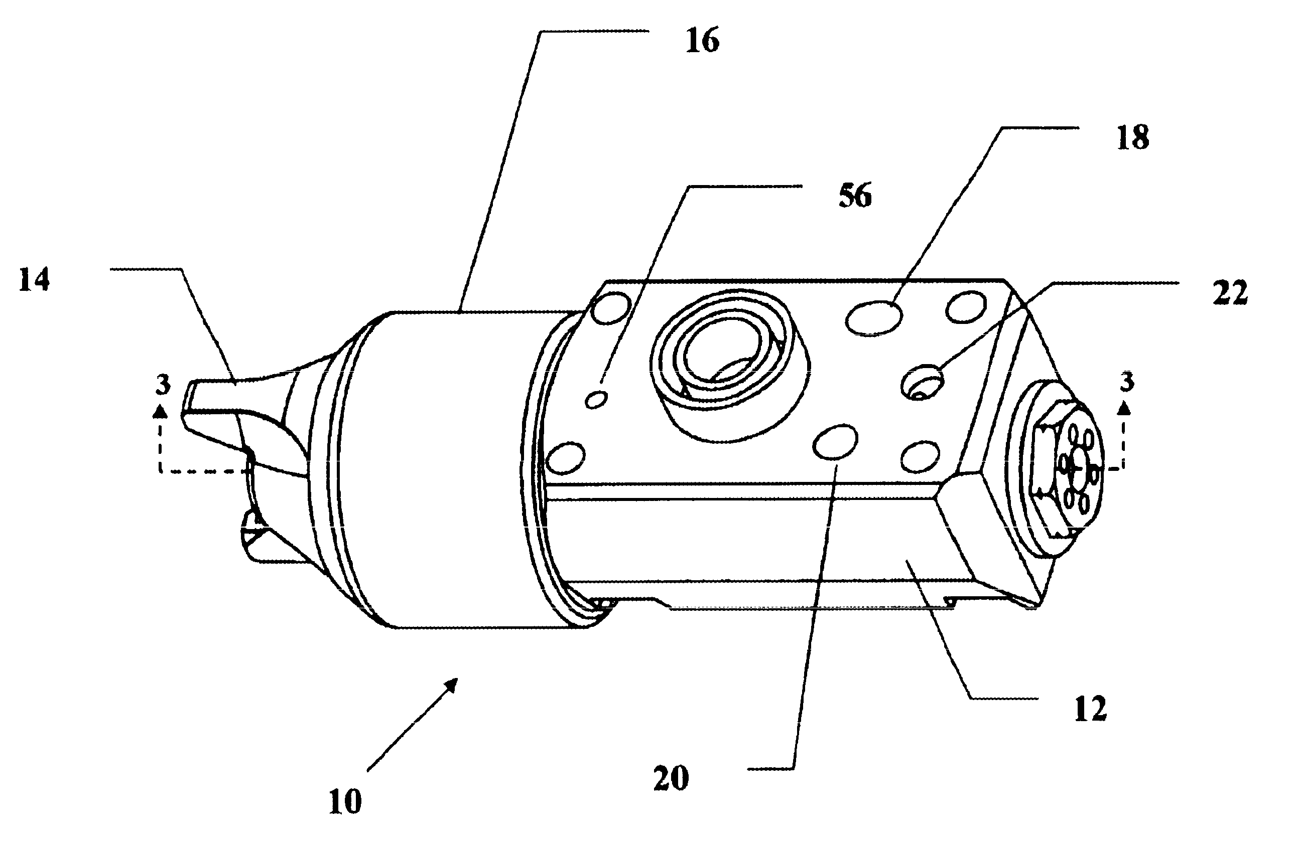
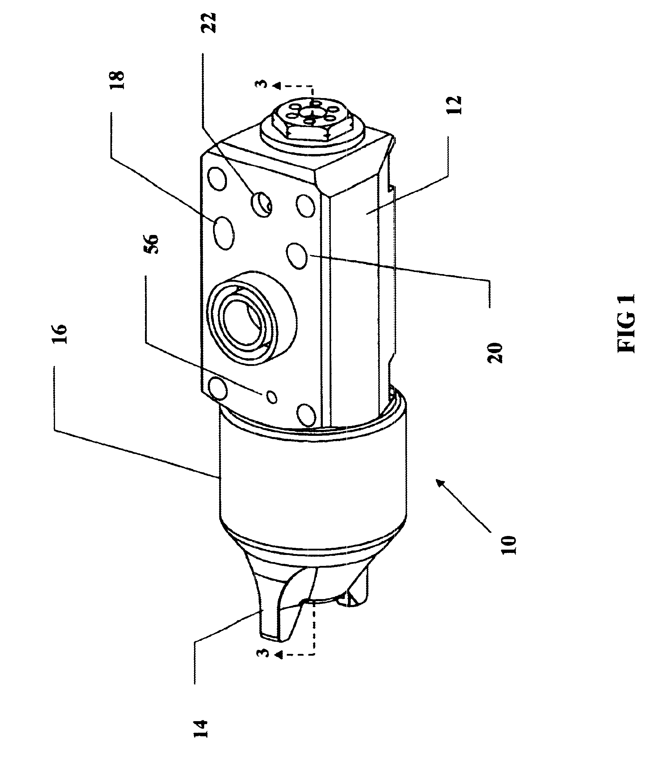
Referring now to FIGS. 1-5, the present invention is a device 10 for spraying paint, especially for robot mounting which can be operated externally of the device and does not require manual activation or use by an operator. However, the present invention can also be used manually by an operator.

The device 10 has a body 12 and an air cap 14, the air cap 14 being threadingly attached to the first end of the body 12 via an air cap nut 16. Fan air is introduced into the second end of the body 12 through a fan air inlet 18. Atomizing air is introduced into the second end of the body 12 through an atomizing air inlet 20. The fan air and atomizing air volume and pressure are each controlled externally of the device by a flow regulator and / or a pressure regulator. The fan air and atomizing air are directed through the body 12 via ducts within the body 12 as will be described.

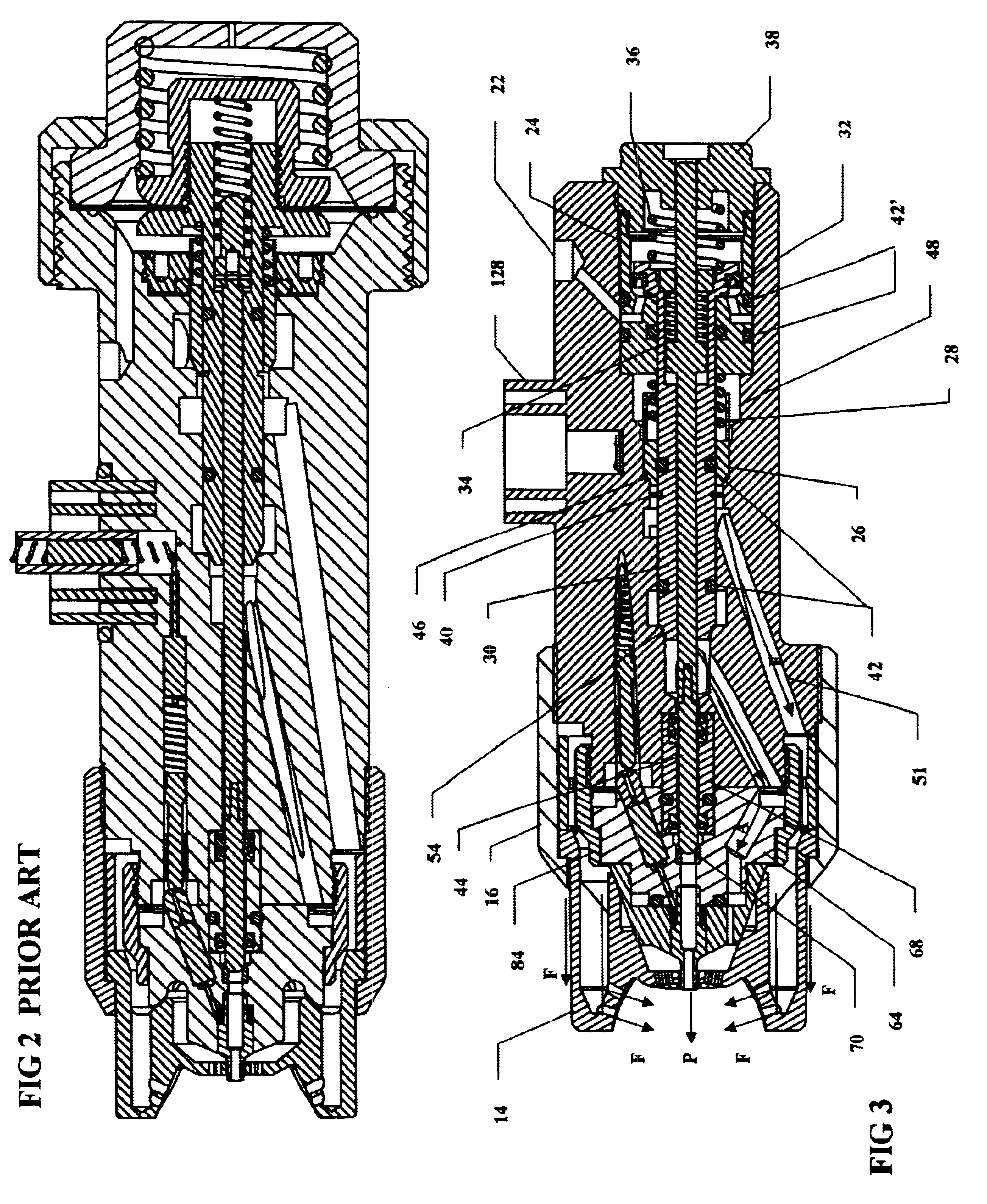
Trigger air is introduced into a trigger air inlet 22 to activate a cartridge. The cartridge has a housing 24, an out...


PUM


Abstract

A device for spraying paint having a spring activated cartridge in a body. The flow of fan air, atomizing air and paint are controlled by pistons within the cartridge. The fan air and atomizing air exit the body through slots to provide high volume, low pressure. The fan air is distributed uniformly by a baffle flange within a guide ring. The fan air exiting the air cap passes through a conical opening. Compensating air is provided over the surface of the air cap for improved coating. Isolation rings for reduction of electrical leakage are integrally formed in the body.

Description

FIELD OF THE INVENTIONThe present invention relates to a paint spraying device and more particularly to a high volume, low pressure device to pattern shape the atomizing and fan air.BACKGROUND OF THE INVENTIONPaint spray devices, or guns, were usually operated at high pressure to atomize the paint and to adjust the spray patterns due to the wide availability of high pressure air. However, the coating transfer efficiency was less than optimum at the high pressures and an undesirable amount of coating material was dispersed into the environment. This led to an increased use of high volume low pressure (HVLP) air operated spray guns due to improved coating transfer efficiency and decreased air pollution. Several approaches have been used to provide the low pressure air and also have high volume air flow. Some of these are disclosed in the following:U.S. Pat. No. Inventor(s) 5,064,119 Mellette 5,090,623 Burns et al 5,135,172 Toth 5,165,605 Morita 5,178,330 Rogers 5,209,405 Robinson et a...

Claims


Application Information

Patent Timeline
IPC IPC(8): B05B7/02B05B7/08B05B7/12B05B7/00
CPCB05B7/0081B05B7/0815B05B7/1254B05B7/1263
Inventor VAN DER STEUR, GUNNAR
Owner EFC SYST
Why Eureka
Try Eureka