Non-magnetic metallic layer in a reader gap of a disc drive

a technology of non-magnetic metallic layer and disc drive, which is applied in the direction of record information storage, manufacturing head surfaces, instruments, etc., can solve the problems of reducing thermal resistance of conducting non-magnetic layers and reaching the limit of type of reader redesign

Inactive Publication Date: 2004-03-02
SEAGATE TECH LLC
View PDF12 Cites 24 Cited by
  • Summary
  • Abstract
  • Description
  • Claims
  • Application Information

AI Technical Summary

Problems solved by technology

Reader stacks can be redesigned to have higher magnetoresistive ratios, however, this type of reader redesign reaches a limit also.
These thermally conducting nonmagnetic layers reduce thermal resistance without a corresponding reduction in the reader magnetic gaps.

Method used


Image

  • Non-magnetic metallic layer in a reader gap of a disc drive
  • Non-magnetic metallic layer in a reader gap of a disc drive
  • Non-magnetic metallic layer in a reader gap of a disc drive

Examples


second embodiment

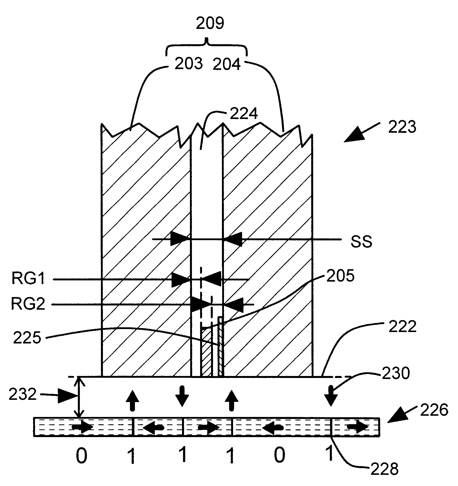
FIG. 7 illustrates an enlarged bottom view of a magnetoresistive read sensor 260 that includes a thermally conducting nonmagnetic layer 262 in a read gap. The arrangement illustrated in FIG. 7 is similar to the arrangement illustrated in FIG. 6 except that in FIG. 7 the nonmagnetic layer 262 is deposited on the bottom magnetic shield layer 203 instead of the shared magnetic shield layer 204. As illustrated in FIG. 7 at lines 264, there is an enhanced heat flow from the magnetoresistor 238 to the bottom magnetic shield layer 203 through the thermally conducting nonmagnetic layer 262.

third embodiment

FIG. 8 illustrates an enlarged bottom view of a magnetoresistive read sensor that includes a thermally conducting nonmagnetic layer in a read gap. The arrangement illustrated in FIG. 8 is similar to the arrangement illustrated in FIGS. 6-7 except that in FIG. 8 the nonmagnetic layer 262 is deposited on the bottom magnetic shield layer 203, and also the nonmagnetic layer 225 is deposited on the shared magnetic shield layer 204. In FIG. 8, each of the two insulating layers 224 is reduced in thickness to accommodate one of the nonmagnetic layers 225, 262. As illustrated in FIG. 8 at lines 264, 266, there is an enhanced heat flow from the magnetoresistor 238 to the bottom magnetic shield layer 203 through the first thermally conducting nonmagnetic layer 262, and there is also an enhanced heat flow form the magnetoresistor 238 to the shared magnetic shield layer 204 through the second thermally conducting nonmagnetic layer 225.

FIG. 9 illustrates a finite element analysis of peak and aver...


PUM

PropertyMeasurementUnit
thicknessaaaaaaaaaa
thicknessaaaaaaaaaa
sizeaaaaaaaaaa

Abstract

A read / write head with a bottom shield on a slider substrate and a shared shield spaced apart from the bottom shield. A write head is deposited on the shared shield. A read sensor is spaced apart by reader magnetic gaps from the bottom shield and the shared shield. Electrically insulating layers in the reader magnetic gaps form a thermal resistance between the read sensor and the shields. A thermally conducting nonmagnetic layer in a reader magnetic gap reduces the thermal resistance without a corresponding reduction in the reader magnetic gaps.

Description

The present invention relates generally to heads for use in a magnetic storage drive. In particular, this invention relates to methods and structures for reader gaps.A read / write head in a disc drive typically includes a magnetoresistive (MR) read sensor that is deposited between insulating layers and magnetic shield layers. The magnetoresistive read sensor typically includes a magnetoresistor stack, electrical contacts and one or more bias magnets that magnetically bias the magnetoresistor stack.The magnetoresistor and electrical contacts carry an electrical bias current. As magnetically stored data on a disc flies by the magnetoresistor, the magnetoresistor generates readback pulses that have a readback amplitude that represents the data stored on the disc. The readback amplitude is generally proportional to the bias current. The bias current amplitude and read sensor dimensions are chosen in a way that considers the needs of the read channel electronics for a high amplitude readb...

Claims


Application Information

Patent Timeline
Patent Type & Authority Patents(United States)
IPC IPC(8): G11B5/31G11B5/39G11B5/40
CPCG11B5/3103G11B5/3133G11B5/3903G11B5/3967G11B5/40
Inventor DIMITROV, DIMITARKAUTZKY, MICHAEL C.GANGOPADHYAY, SUNITA B.RAMDULAR, JUMNA P.BOUNNAKHOM, SISAVATH M.TSU, I-FEILAMBERTON, ROBERT W.
Owner SEAGATE TECH LLC
Why Eureka
Try Eureka