Machine for chip cutting machining plus cutting tool for such machines

a technology for cutting tools and machines, applied in the direction of tool holders, shaping cutters, manufacturing tools, etc., can solve the problems of difficult mastery, obvious risk of jets intersecting, and tools that are not suitable for mastering, so as to reduce the consumption of cooling liquid and achieve the greatest possible cooling and chip breaking effect.

Inactive Publication Date: 2004-03-23
SANDVIK INTELLECTUAL PROPERTY AB
View PDF8 Cites 39 Cited by
  • Summary
  • Abstract
  • Description
  • Claims
  • Application Information

AI Technical Summary

Benefits of technology

is to provide a cutting tool by means of which high pressure cooling liquid jets may be directed at one or more cutting edges on one and the same cutting insert while achieving a jet angle, which for each given geometry is optimally independent of which edge portion that is active during a machining operation. Another object is to create a cutti...

Problems solved by technology

However, when this insight into the importance of the jet angle is to be put into practice, a phenomenon which is difficult to master presents itself, viz. the fact that the operative part of a cutting insert may "migrate" during a machining operation.
Although the high pressure liquid nozzles which are included in the cutting tool known from WO 99/39852 are adjustable in different positions in order to direct the high pressure liquid jets to different points of impact on a cutti...

Method used


Image

  • Machine for chip cutting machining plus cutting tool for such machines
  • Machine for chip cutting machining plus cutting tool for such machines
  • Machine for chip cutting machining plus cutting tool for such machines

Examples


Embodiment Construction

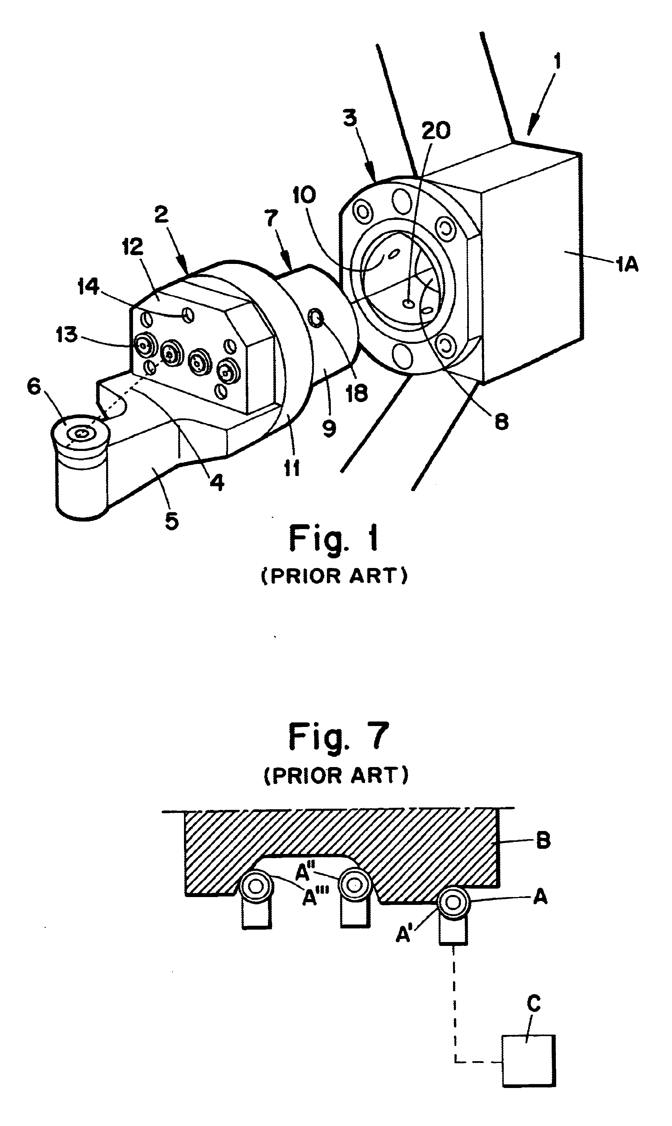
In FIG. 1, a machine intended for chip cutting machining is generally outlined at the reference designation 1. More precisely, the machine is illustrated in the form of a portion of a rotatable turret plate, which in practice includes a plurality of different tools. One such tool is generally designated 2 and is in the form of a so called cutting unit, which co-operates with a holder in the form of a clamping unit 3. The cutting unit 2 may be detachably clamped in a fixed position in the clamping unit 3. The cutting unit 2 includes a front part 5 with a detachable cutting insert 6, which in the embodiment according to FIGS. 1-2 is exemplified in the form of a round cutting insert. A rear part 7 of the cutting unit 2 is in the shape of a male element, which is insertable in a cavity 8 in the clamping unit 3. The coupling between the cutting unit and the clamping unit may advantageously be of the type COROMANT CAPTO.RTM., the male element 7 as well as the cavity 8 having a polygonal, ...


PUM


Abstract

A cutting tool (2) includes a front part (5), which has a cutting insert (6), as well as a rear part (7), which is detachably mountable in a holder (3) in an appurtenant machine. The tool (2) comprises a plurality of nozzles (13), which have the purpose of spraying jets (4) of high pressure cooling liquid towards the cutting insert (6). Supply of cooling liquid to these nozzles is guaranteed via a duct system positioned inside the tool, which system includes an equally large number of mutually spaced-apart ducts as the number of nozzles, the nozzles being adjusted in order to direct the jets thereof towards different points of impact on one and the same cutting insert. In this connection, it is possible to close the individual ducts inside the tool individually in order to enable spraying of only one jet at a time towards the appurtenant point of impact on the cutting insert.

Description

TECHNICAL FIELD OF THE INVENTIONIn a first aspect, this invention relates to a machine intended for chip cutting machining, in particular metalworking, of the type that comprises one or more cutting tools with a front part, which has at least one cutting insert, as well as a rear part, which is detachably fixed in a permanent holder in the machine, the tool including a plurality of nozzles, which have the purpose of spraying jets of high pressure cooling liquid towards the cutting insert and which are supplied with pressurised cooling liquid from at least one liquid supply source, more precisely via a system of ducts inside the tool.GENERAL BACKGROUND OF THE INVENTION AND PRIOR ARTThe practice of cooling not only the cutting inserts of a cutting tool, e.g. tools for turning, but also the workpiece commonly consisting of metal which is machined by the tool has been known for a long time. A primary aim of today's technology for cutting or chip cutting machining is to enable use of as ...

Claims


Application Information

Patent Timeline
IPC IPC(8): B23Q11/10B23B29/00B23B29/04B23Q1/00B23Q11/00B23B27/10B23B27/22B23B29/12
CPCB23B29/046B23Q1/0018B23Q11/10B23B27/10Y10T407/14Y10T407/2268Y10T407/245Y10T82/16065
Inventor LAGERBERG, STIG
Owner SANDVIK INTELLECTUAL PROPERTY AB
Why Eureka
Try Eureka