Loading device for ISO containers

a technology for loading devices and containers, applied in waterborne vessels, special purpose vessels, cranes, etc., can solve the problems of not being able to meet the needs of tank containers or other special containers, not being able to guarantee the safety of the container, and increasing the investmen

Inactive Publication Date: 2004-04-06
GOTTWALD PORT TECH
View PDF14 Cites 23 Cited by
  • Summary
  • Abstract
  • Description
  • Claims
  • Application Information

AI Technical Summary

Benefits of technology

The proposed loading device appreciably increases the loading and unloading capacity of the container bridge. It replaces the second trolley traveling mechanism in the container bridge and makes it possible to rotate the containers by at least 90.degree. so that they arrive from the transporting position in the ship to the unloading position in the transporting vehicle. The at least two loading stations which are provided constitute an intermediate storage for the containers which is movable on traveling mechanisms from the loading area to the off-loading or on-loading area of the transporting vehicle.
According to a special feature of the invention, it is provided that every bridge member of every loading station is angled upward in an L-shaped manner and, by means of a rail traveling mechanism arranged at its upward angled end, is movable on a horizontal running rail which is arranged at a longitudinal member fastened to the supporting construction of the container bridge transverse to the boom. In this construction, the loading stations are connected in a positive engagement with the container bridge, wherein the construction allows the container bridge to move relative to the loading stations and the loading stations to move relative to the container bridge.
According to a further feature of the invention, another running rail extending parallel to the horizontal running rail is arranged at the underside of the longitudinal member and another rail traveling mechanism fastened to a tilting moment support of the loading station rolls on this running rail. This tilting moment support at the water-side rail traveling mechanism protects the loading station against tilting moments which can occur, for example, in the event of asymmetric loading of the receiving platform.
It is particularly advantageous when the receiving platform of every loading station is provided in the areas contacted by the corners of the storable ISO container with recesses for gripping and handling the twistlock connections. When the receiving platform is located in the on-loading or off-loading position in the direction of the longitudinal axes of the L-shaped bridge member, the twistlock at the corner fittings of the container can be assembled and disassembled without difficulty through the recesses by the personnel responsible for this task.
A partial overlapping of the rotating movement and transverse movement would be possible for the purpose of reducing cycle time (e.g., the transverse movement is initiated after 1 / 3 of the rotating movement).
The novel arrangement is advantageous as an economical addition to known loading and unloading equipment because the loading device replaces a second trolley in the container bridge. Therefore, the costs of acquiring and maintaining are appreciably lower compared to conventional solutions such as those suggested in the prior art taken as a point of departure by the invention. The loading device is suitable for full automation and can also be retrofitted to existing systems. The capacity of the container terminal can be noticeably increased by the invention because two to three loading tracks can be serviced by one trolley traveling mechanism with the loading device. Time-critical sequences in terminal logistics management are prevented by the deliberate control of the container bridge in backreach by the AGVs or straddle carriers. The quantity of required container transport vehicles can accordingly be reduced.

Problems solved by technology

However, the known solution is disadvantageous because although the use of the second crane trolley in the container bridge increases handling capacity, it results in additional relatively high investment, servicing and maintenance costs.
Further, the platform for mounting and removing the twistlocks is not suitable for the handling of tank containers or other special containers (e.g., refrigerated containers or containers for shipping automobiles).
However, this is not always guaranteed in the case of special containers.

Method used


Image

  • Loading device for ISO containers
  • Loading device for ISO containers
  • Loading device for ISO containers

Examples


Embodiment Construction

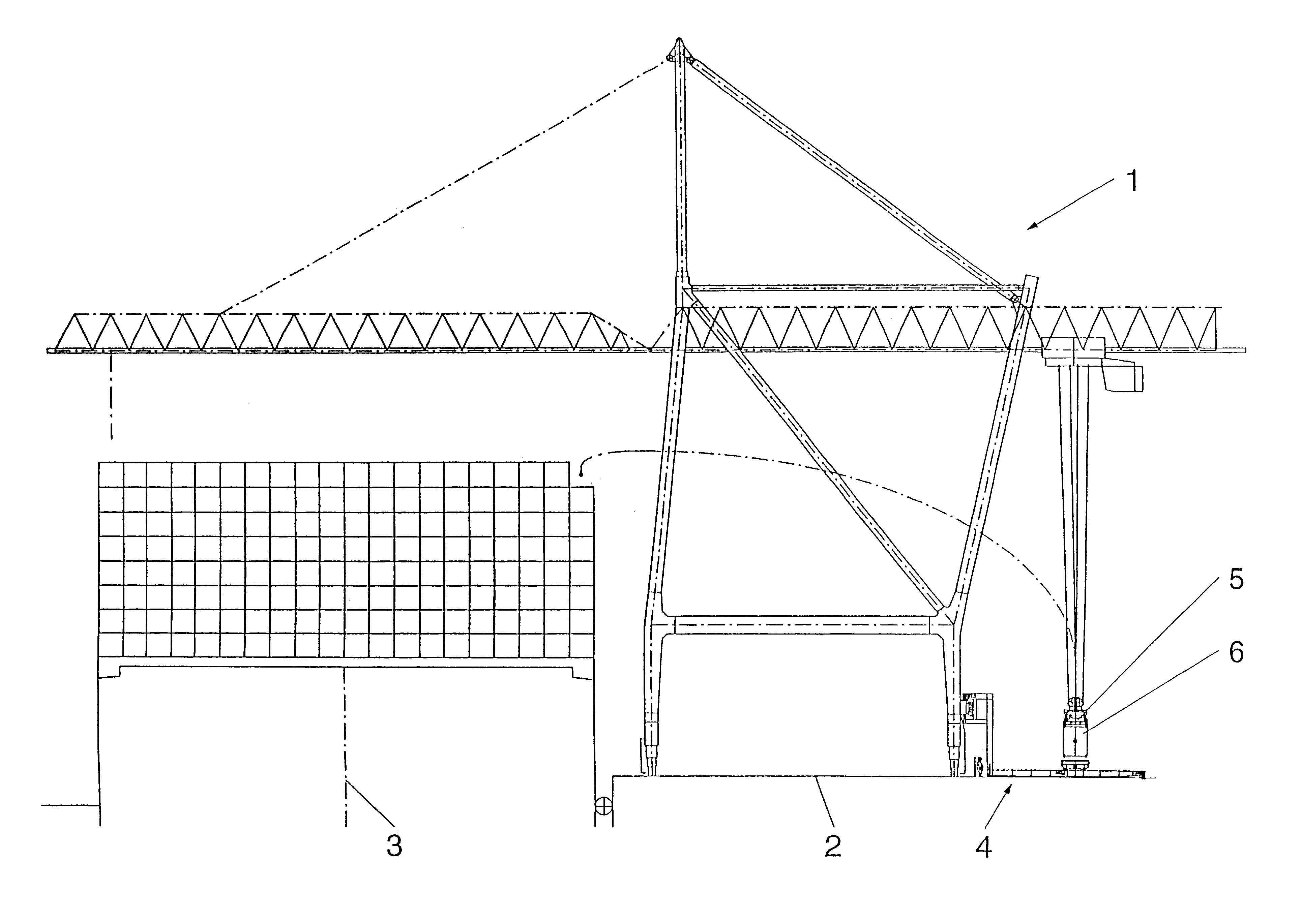
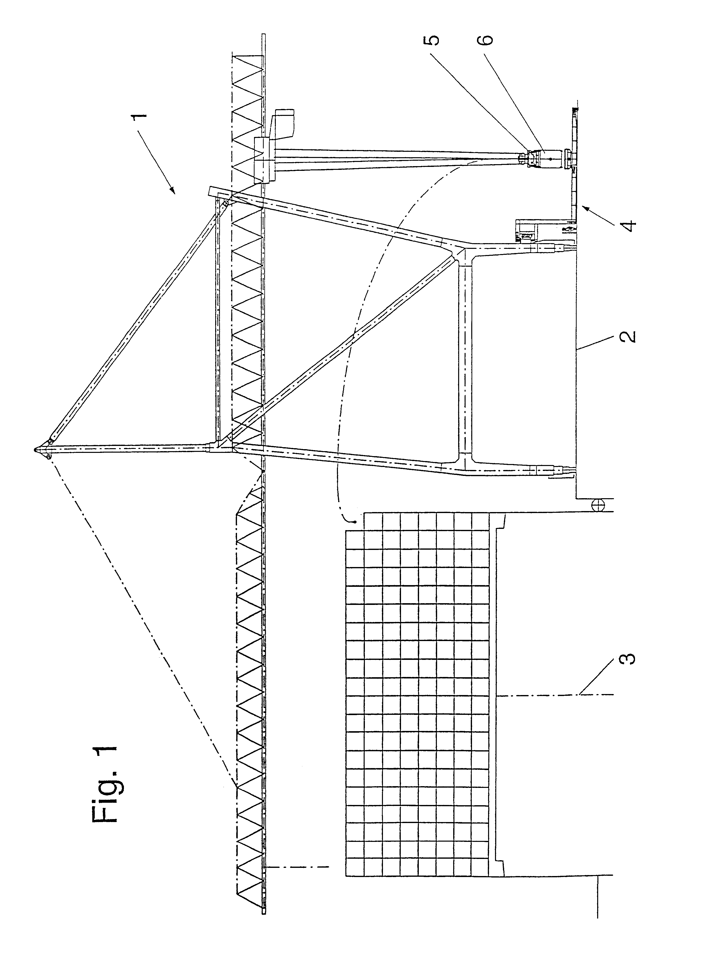
In an overall view of the pier installation of a container terminal, FIG. 1 shows a container bridge 1 by which a container ship 3 lying off a pier 2 is loaded. For this purpose, an additional loading device 4 according to the invention is provided at the rear side of the container bridge remote of the ship. The container 6 is suspended from a spreader 5 which is movable by a trolley traveling mechanism at a boom which extends on the water-side over the ship and projects over the supporting construction of the container bridge at its opposite side.

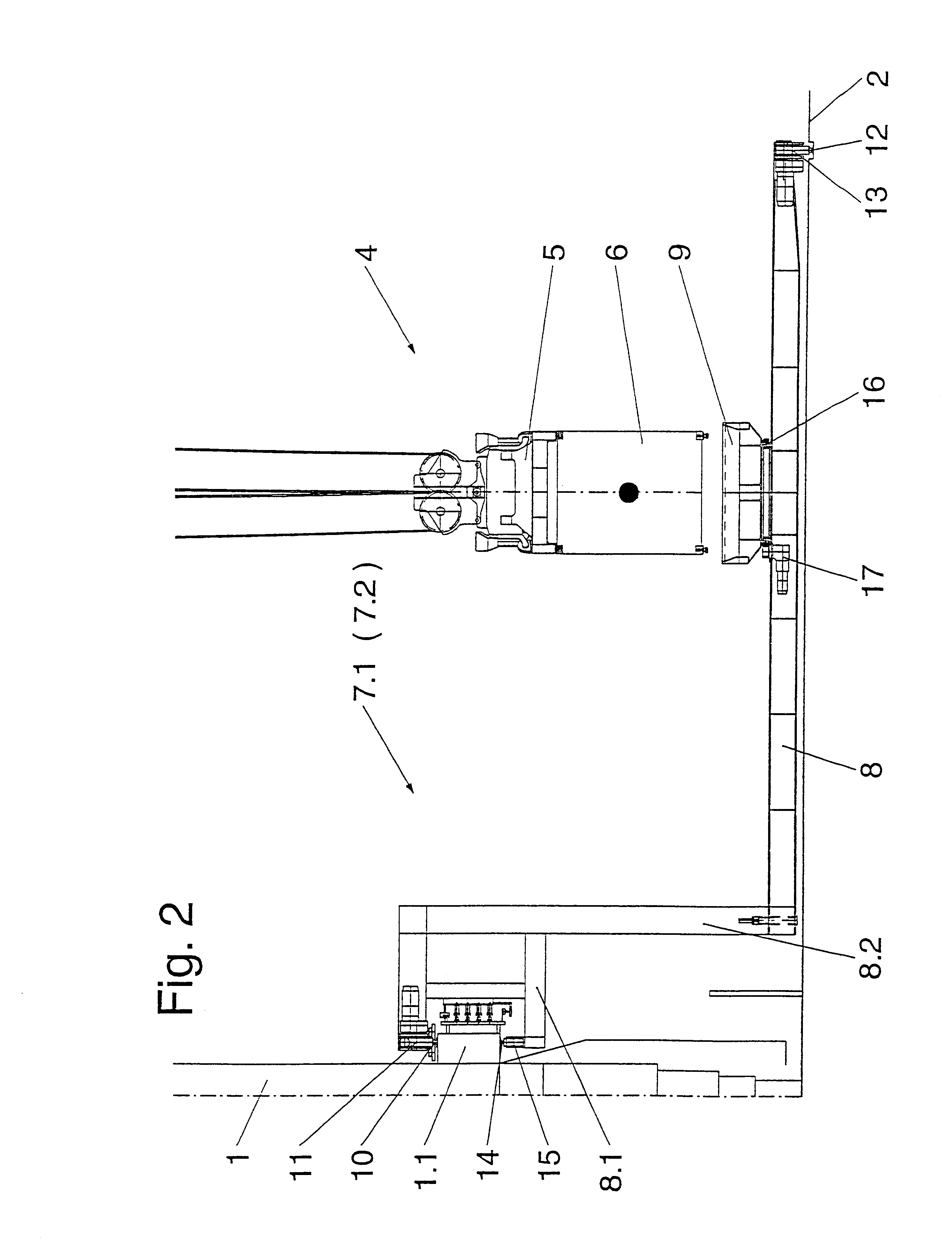
FIG. 2 is a detailed view of the loading device 4 showing one of two loading stations 7.1 and 7.2. Each loading station comprises an L-shaped bridge member 8 and the rotating receiving platform 9. The upper side of the longitudinal member 1.1 of a crane path which is supported at the container bridge 1 forms the base for a crane rail 10. The L-shaped bridge member 8 is supported on the crane rail 10 by its water-side rail traveling mechani...


PUM


Abstract

A loading device for ISO containers in a container terminal is arranged below the land-side boom in the rear area of the container bridge and cooperates with container transport vehicles. The loading device comprises at least two bridge members which are movable on the ground independent from one another transverse to the longitudinal axis of the boom, and are oriented parallel to one another and to the boom. Each bridge member forms a loading station for an ISO container and carries in the area of its longitudinal center a receiving platform for an ISO container which can be set down and picked up by load-carrying means, this receiving platform being rotatable about a vertical axis.

Description

1. Field of the InventionThe invention is directed to a loading device for ISO containers in a container terminal for loading and unloading ships with a container bridge, a boom which extends at the gantry frame of the container bridge over its supporting construction on the water side and on the land side, and running rails for a crane trolley with container load-carrying means provided at the boom for transporting the container from ship to pier, and vice versa, wherein the loading device is arranged below the land-side boom in the rear area of the container bridge and cooperates with container transport vehicles.2. Description of the Related ArtGerman Utility Model 279 19 466 discloses a loading and unloading system for containers which uses a container bridge formed by a gantry frame. The gantry frame is supported on a traveling mechanism which is movable along the rails parallel to the pier at which the ship is docked. The gantry frame has a boom extending over the supporting c...

Claims


Application Information

Patent Timeline
Patent Type & Authority Patents(United States)
IPC IPC(8): B66C19/00B65G67/60B65G63/00
CPCB66C19/002B65G67/60
Inventor DOBNER, MATHIASFRANZEN, HERMANNKROLL, JOACHIM
Owner GOTTWALD PORT TECH
Why Eureka
Try Eureka