Supercharge Your Innovation With Domain-Expert AI Agents!

Resiliently bonded heat exchanger

a heat exchanger and resilient technology, applied in the field of heat exchangers, can solve the problems of affecting the life of heat exchangers of many types, affecting the efficiency of heat exchangers,

Inactive Publication Date: 2004-04-13
VISTA PRO AUTOMOTIVE
View PDF26 Cites 31 Cited by
  • Summary
  • Abstract
  • Description
  • Claims
  • Application Information

AI Technical Summary

Benefits of technology

"The present invention provides a method of manufacturing a heat exchanger with long-life properties. The method involves using a flexible, bonded, liquid tight, tube-to-header joint instead of traditional methods that use compression fits or soldering. This joint is created by applying uncured fluid sealing material to the openings in the header and tubes, and then curing it to create a strong, flexible connection. The use of this sealing material provides a more reliable and durable joint, and the method is simpler and more cost-effective than traditional methods. The invention also includes a resilient tank to header joint and a resilient joint between the tubes and header. These improvements make the heat exchanger more durable and easier to assemble."

Problems solved by technology

Heat exchangers of many types, such as radiators, charge air coolers, oil coolers and the like, suffer limited life as a result of high working stresses at their tube-to-header joints.
Since the tubes are usually rigidly attached to a relatively inflexible header by means of soldering, brazing, welding or the like, the resulting stresses ultimately lead to joint fatigue failure or tube fatigue in the area next to the joint.
The heat exchanger assembly involves the tedious handling of numerous small parts (the grommets), and lacks any real bond between the tubes and the headers, relying solely on the compression fit to provide a seal.
A major disadvantage of this design is that sealing is dependent on providing and maintaining a compression fit between the grommet, tube, and header.
The disadvantages of specially made resilient headers include the substantial amount of skill and labor required to solder the tubes and headers together.
Also, the specially molded resilient headers are extremely expensive to produce.

Method used


Image

  • Resiliently bonded heat exchanger
  • Resiliently bonded heat exchanger
  • Resiliently bonded heat exchanger

Examples


Embodiment Construction

)

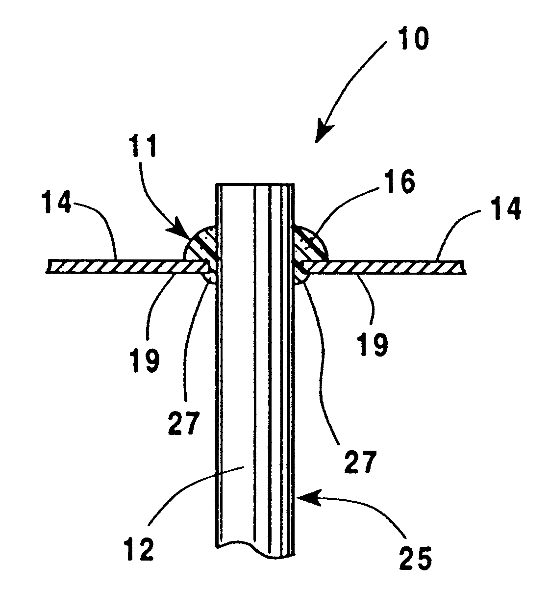
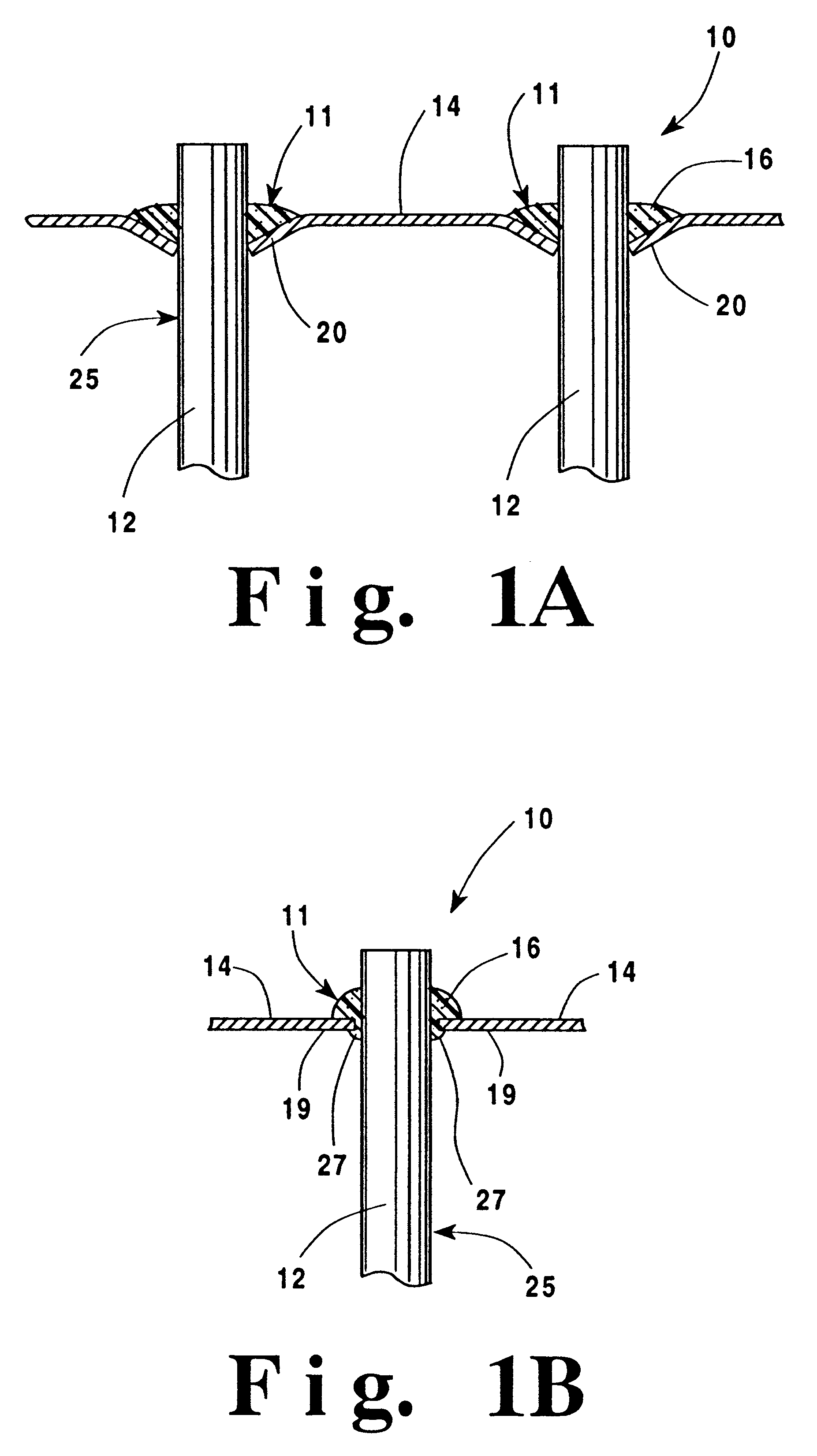
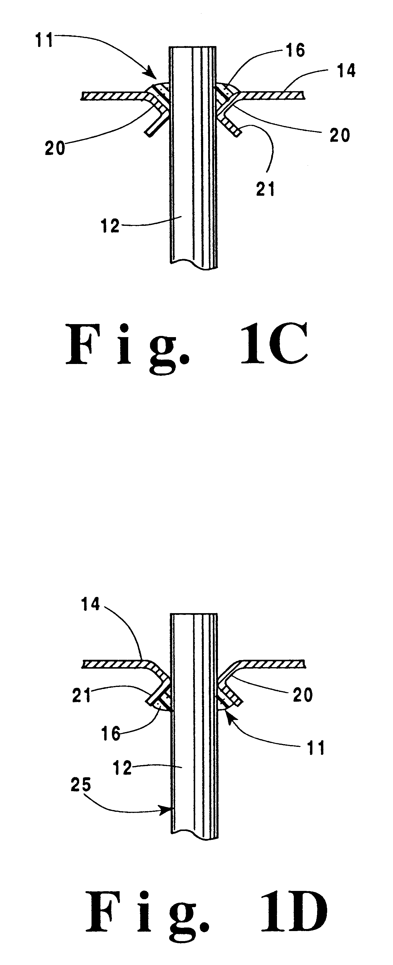
In describing the preferred embodiments of the present invention, reference will be made herein to FIGS. 1-10 of the drawings in which like numerals refer to like features of the invention. Features of the invention are not necessarily shown to scale in the drawings.

Generally, the present invention provides a method of producing flexible liquid tight seals using formed in place and cured in place techniques. The seal can be provided in a tank-to-header joint or a tube-to-header joint. Curing the seal after the assembly of the parts has specific advantages including providing a bonded liquid tight sealing joint instead of a compression fit sealing joint, and enhanced ease of assembly. Moreover, other advantages using the present invention include the expansion and contraction of the flexible joints when other components of the heat exchanger are also expanding and contracting. Also, the flexible nature of the joints provides a long life heat exchanger. Further, the present invention...


PUM

PropertyMeasurementUnit
flexibleaaaaaaaaaa
dimensionaaaaaaaaaa
temperatureaaaaaaaaaa

Abstract

A heat exchanger and method of making a heat exchanger which includes providing a header having openings adapted to receive a plurality of tubes. The tubes are inserted into the header openings, then, substantially uncured fluid sealing material is applied to at least the inner surfaces of the header openings. The inner surfaces of the header openings and the outer surfaces of the tubes are connected by the sealing material. The method further includes curing the sealing material after the tubes are inserted into the header openings. The sealing material thus provides a flexible, bonded, liquid tight, tube-to-header joint.

Description

1. Field of the InventionThis invention relates to heat exchangers and, more particularly, to heat exchangers utilizing tube-to-header joints.2. Description of Related ArtHeat exchangers of many types, such as radiators, charge air coolers, oil coolers and the like, suffer limited life as a result of high working stresses at their tube-to-header joints. These stresses are a result of thermal expansion and contraction of the tubes, thermal changes in header length, and variations in internal pressure during operation. Since the tubes are usually rigidly attached to a relatively inflexible header by means of soldering, brazing, welding or the like, the resulting stresses ultimately lead to joint fatigue failure or tube fatigue in the area next to the joint.In an effort to minimize or eliminate the stresses described above, some heat exchangers have been made with grommeted tube-to-header joints. In such heat exchangers, tube openings in the headers are made to be oversize with respect...

Claims


Application Information

Patent Timeline
Patent Type & Authority Patents(United States)
IPC IPC(8): F28F9/02F28F9/04F28F9/16F28F21/06
CPCF02B29/0456F28F9/02F28F9/0226F28F9/162Y10T29/49373F28F21/067Y02T10/146Y02T10/12
Inventor CROOK, RICHARD F.
Owner VISTA PRO AUTOMOTIVE
Features
  • R&D
  • Intellectual Property
  • Life Sciences
  • Materials
  • Tech Scout
  • Unparalleled Data Quality
  • Higher Quality Content
  • 60% Fewer Hallucinations
Learn More