Projectile firing apparatus

a firing apparatus and projectile technology, applied in the field of projectile firing apparatus, can solve the problems of significant time required to position, significant constraint on the application or utility of the equipment, and relative slow rate of grenade delivery, and achieve the effect of reducing the set-up tim

Inactive Publication Date: 2004-04-20
METAL STORM LIMITED ACN 064 370 006
View PDF17 Cites 55 Cited by
  • Summary
  • Abstract
  • Description
  • Claims
  • Application Information

AI Technical Summary

Benefits of technology

Such pods will require minimal set-up time for firing many projectiles at a selected target

Problems solved by technology

Accordingly the relatively slow rate of delivery of grenades provides a significant constraint on the applications or utility of the equipment.
Barrels assemblies of the type described have the disadvanta

Method used


Image

  • Projectile firing apparatus
  • Projectile firing apparatus
  • Projectile firing apparatus

Examples


Embodiment Construction

In order that this invention may be more readily understood and put into practical effect, reference will now be made to the accompanying drawings which illustrate typical embodiments of the invention, wherein:

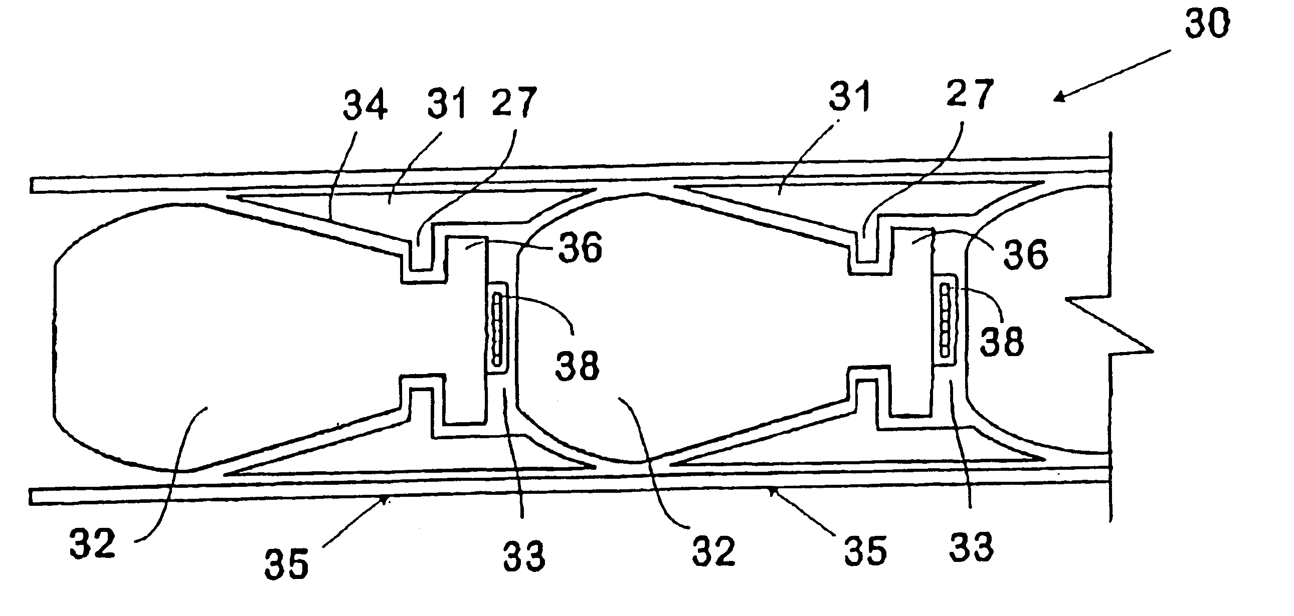
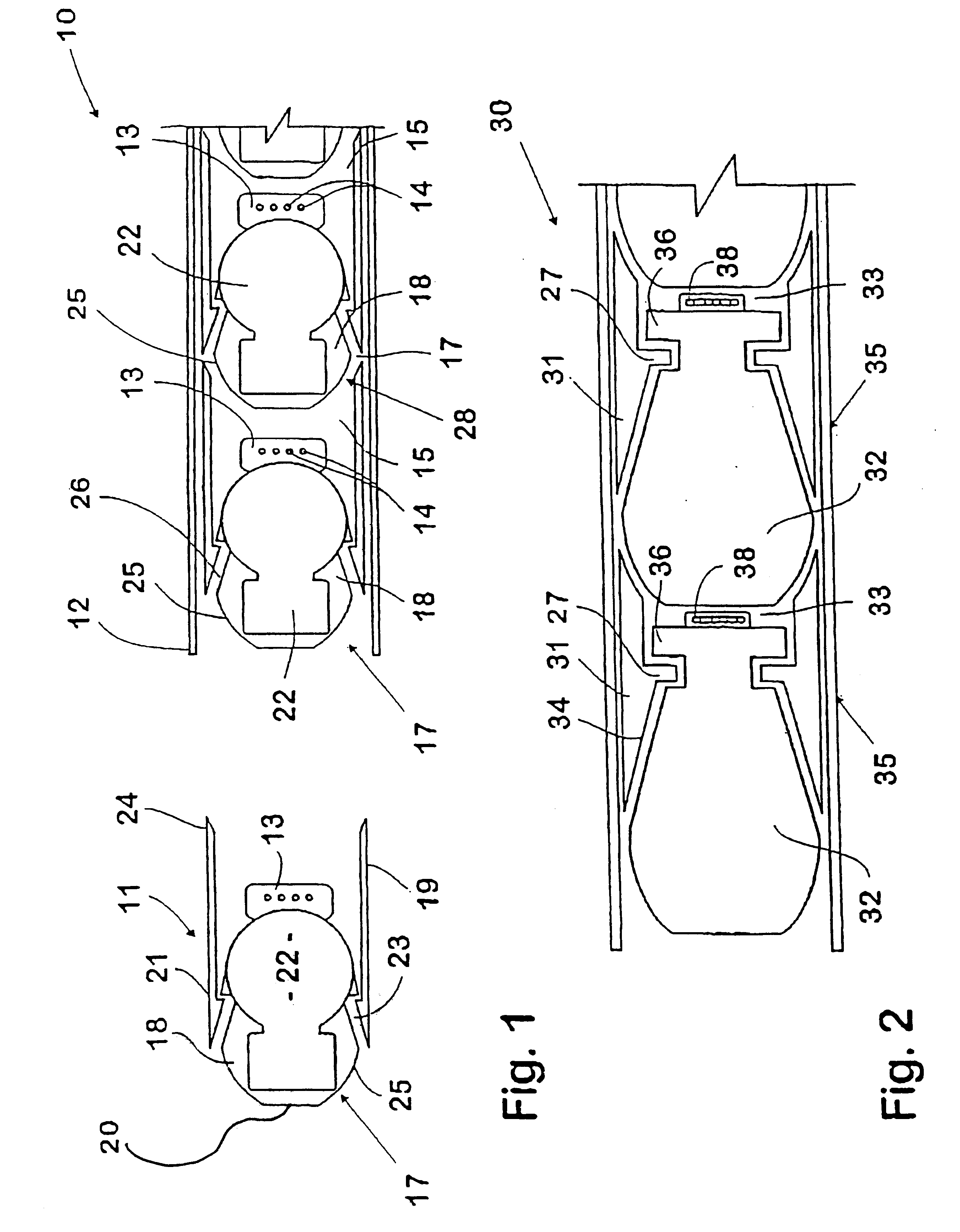
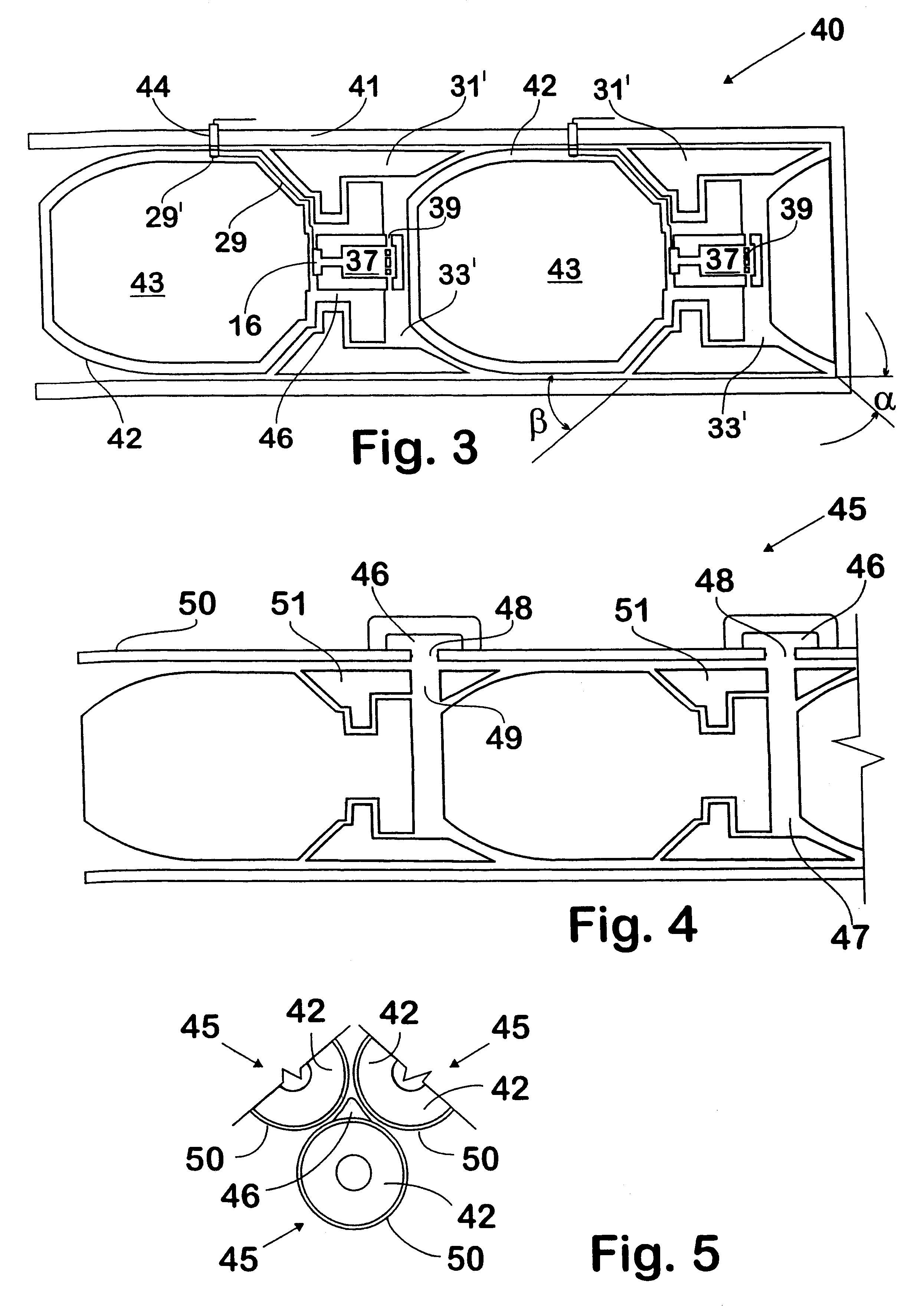
FIGS. 1 to 4 diagrammatically illustrate typical barrel assemblies according to this invention;

FIG. 5 is a diagrammatic cutaway end view of a cluster of barrel assemblies;

FIG. 6 illustrates a pod of grenade firing barrel assemblies;

FIG. 7 illustrates a typical application of the present invention;

FIG. 8 illustrates a further application of the invention utilising an unmanned aerial vehicle;

FIG. 9 is an underside view of one of the pod carriers of the aerial vehicle of FIG. 8;

FIG. 10 is a diagrammatic cross-sectional view of a pod of splayable barrel assemblies, and

FIG. 11 illustrates a typical application of one aspect of this invention.

The barrel assembly 10 illustrated in FIG. 1 has multiple grenade carrying projectiles 11 of substantially known form loaded in a rifled barre...


PUM


Abstract

A weapon comprising a transportable pod having a plurality of barrel assemblies (10) of the type including a plurality of projectiles (11) arranged in-line within barrel (12). Each projectile (11) is associated with a discrete, selectively ignitable propellant charge (13) for propelling each projectile (11) sequentially through the muzzle of the barrel (12). Each projectile (11) includes projectile body (22) which matter or objects may be transported. Projectiles (11) are arranged with one another and barrel (12) so as to prevent rearward travel of an ignited propellant charge to the trailing propellant charge. The pod can include a direction control means for selectively varying the relative alignment between barrel assembles (10) so as to selectively vary the relative delivered position of projectile (11) fired from different barrels (12). The weapon may be used for military or civilian applications.

Description

This invention relates to projectiles and firing apparatus therefore and it has particular application to methods of and apparatus for firing projectiles for military use, although this invention is also applicable to civilian uses such as described in our simultaneously filed International application.The military applications of firing projectiles are well known, such as firing grenades, firing radar deflecting chaff and missile decoy packages. In military applications such as firing grenades, each cartridge case carries a projectile assembly containing a single grenade. Accordingly the relatively slow rate of delivery of grenades provides a significant constraint on the applications or utility of the equipment.This invention has particular application to projectiles which are fired from a barrel having a plurality of projectiles arranged in-line within the barrel and which are associated with discrete selectively ignitable propellant charges for propelling the projectiles sequent...

Claims


Application Information

Patent Timeline
IPC IPC(8): F41A21/00F41A21/06F42B39/00F42B5/00F42B5/03F42B39/26F41F1/00F41F1/08F41A19/65
CPCF41A21/06F41F1/08F41F1/085F42B5/035F42B39/26F41F1/00
Inventor O'DWYER, JAMES MICHAEL
Owner METAL STORM LIMITED ACN 064 370 006
Why Eureka
Try Eureka