Trench shoring extraction device

a technology of extraction device and trench shoring, which is applied in the direction of shaft equipment, shaft lining, building rescue, etc., can solve the problems of time-consuming, difficult and dangerous removal of trench shoring, and difficulty in applying an even and distributed force to the trench shoring using an excavator alone, etc., to achieve the effect of reducing the number of set up time and being convenient to travel to and from the excavation si

Active Publication Date: 2010-02-09
JOHN J BRENNAN CONSTR
View PDF14 Cites 0 Cited by
  • Summary
  • Abstract
  • Description
  • Claims
  • Application Information

AI Technical Summary

Benefits of technology

[0009]It is a further object of the present invention to provide such a device that is readily portable to and from the excavation site with minimum set up time required.

Problems solved by technology

Given the significant load upon the trench shoring from the adjacent earth, particularly during or after backfilling, removal of the trench shoring can be difficult and dangerous.
However, the application of an even and distributed force to the trench shoring is difficult to achieve using an excavator alone.
The process is time consuming, difficult and can in some circumstances result in damage to the trench shoring or in ground structure.
Furthermore, significant wear is put on the excavator when removing trench shoring.

Method used


Image

  • Trench shoring extraction device
  • Trench shoring extraction device
  • Trench shoring extraction device

Examples


Embodiment Construction

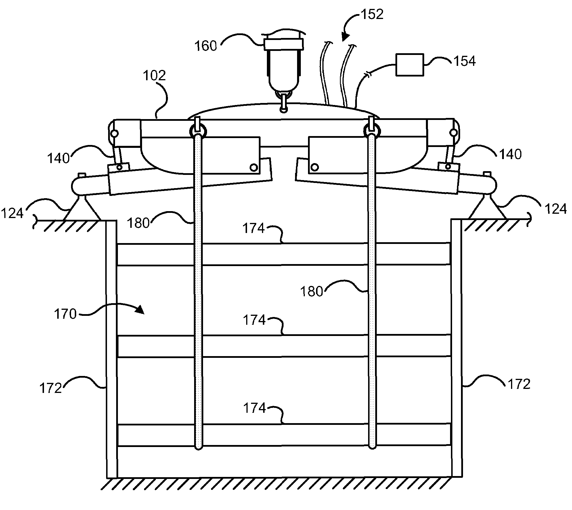
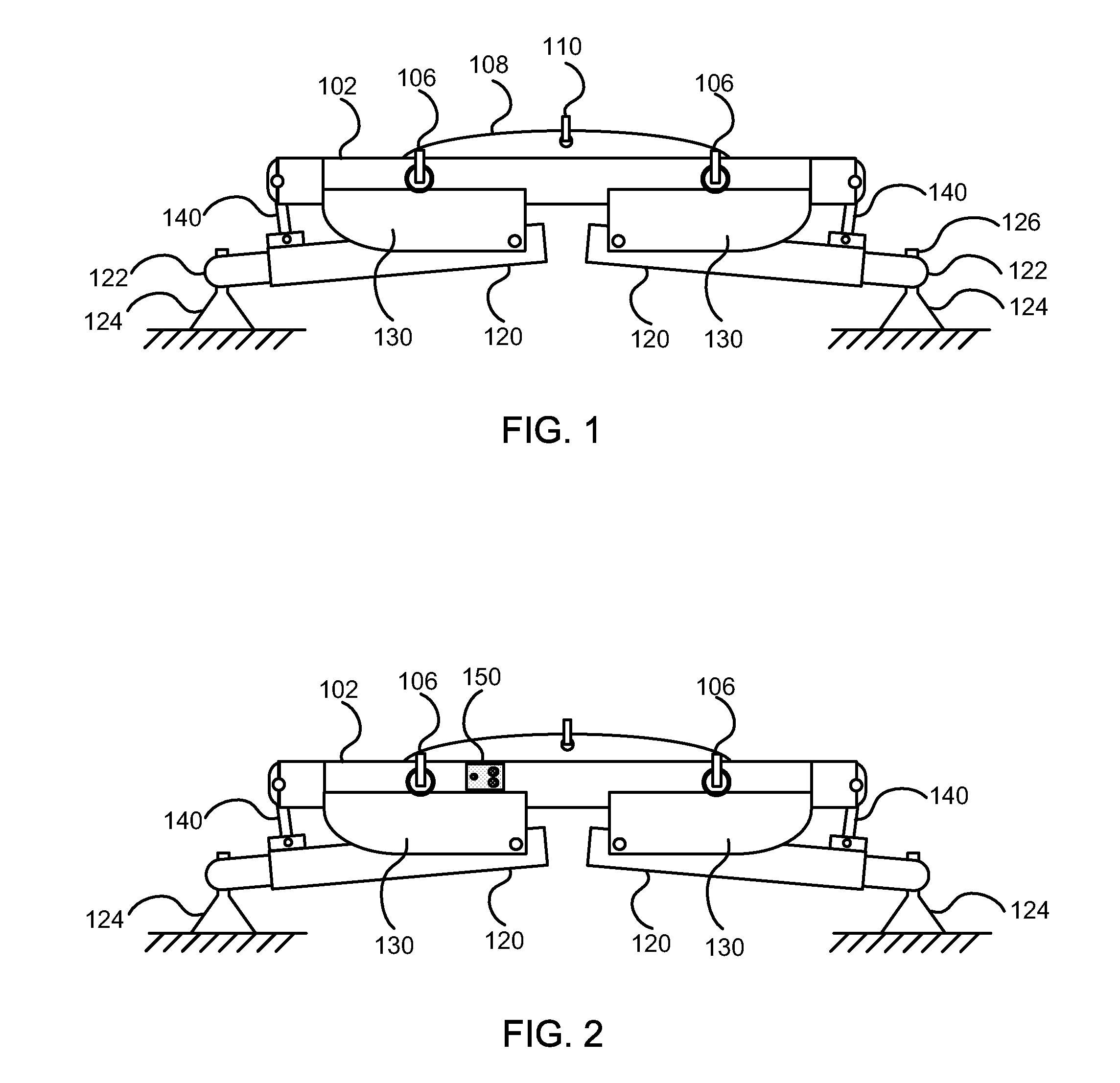
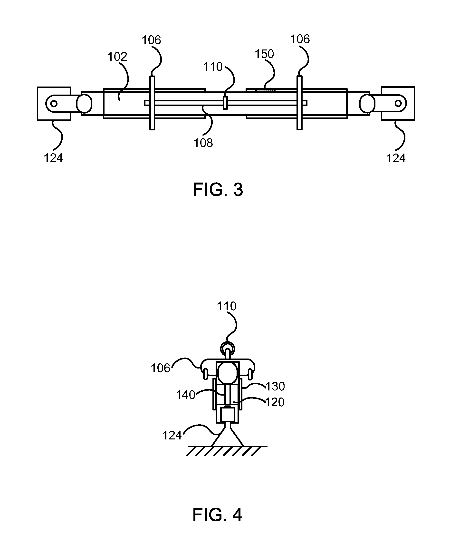
[0025]FIGS. 1-5 illustrate a device according to an exemplary embodiment of the present invention. The device may be useful in a wide variety of vertical lifting applications, and particularly for lifting objects from an in ground or subterranean trench. For example, the device may be used for the extraction of trench shoring.

[0026]The device of the present invention includes a beam 102. The beam 102 of the present exemplary embodiment has a 300 ton maximum capacity. In the exemplary embodiment, the beam is a fixed length beam. However, the beam 102 may also be extendable to accommodate a variety of trench widths. For example, the beam 102 may include one or more extension portions, e.g., in the middle of the beam (not shown).

[0027]The beam 102 includes two or more load connectors 106. In the exemplary embodiment, each load connector 106 is fixed to the beam 102 and includes two or more pulling lugs for receiving slings 180 (shown in FIGS. 6-8) or any other load attachment means. Th...


PUM


Abstract

A hydraulic lifting device including a main beam, two or more connection plates fixedly connected to the main beam, at least two legs, each leg pivotably attached to two of the plates, at least two hydraulic cylinders, each cylinder disposed between the beam and one of the legs, and two or more load connectors.

Description

CROSS-REFERENCE TO RELATED APPLICATIONS[0001]This application claims priority under 35 U.S.C. §119(e) to the filing date of the U.S. Provisional Application No. 60 / 894,058, filed on Mar. 9, 2007.FIELD OF THE INVENTION[0002]The invention relates to a hydraulic lifting device, and more specifically to a hydraulic lifting device and system for extracting shoring materials from an in ground trench.BACKGROUND OF THE INVENTION[0003]Trench shoring is a process of bracing the walls of a trench in order to prevent collapse. This process is often necessary in the construction field when excavating trenches to lay water and sewer pipes, foundations, cables or underground structures.[0004]Typically the side walls of the trench are lined with one or more boxes or vertical shoring panels. A series of boxes or panels may be successively connected to create a continuous shoring wall on either side of the trench. Several horizontal shoring devices or spreaders may be installed between opposing panel...

Claims


Application Information

Patent Timeline
Patent Type & Authority Patents(United States)
IPC IPC(8): E02D17/00
CPCE02D9/02E02D17/086
Inventor THOMPSON, ALAN D.
Owner JOHN J BRENNAN CONSTR
Why Eureka
Try Eureka