Powder compacting machine

a compacting machine and powder technology, applied in dough shaping, baking, food shaping, etc., can solve the problems of inability to replace quickly, inability to prevent the accumulation of waste in the compacting machine, and the substantial bearing force of the lever action of the cantilevered bearing, etc., to achieve the effect of high stability and rapid replacemen

Inactive Publication Date: 2006-09-26
TELLER BERND +1
View PDF11 Cites 0 Cited by
  • Summary
  • Abstract
  • Description
  • Claims
  • Application Information

AI Technical Summary

Benefits of technology

[0010]It is therefore the object of the invention to improve the known compacting machine so that it has high s

Problems solved by technology

A particular problem with such compacting machines designed for small-batch processing is the inevitable waste that remains in the compacting machine after the processing of the batch.
However, a serious disadvantage of the cantilevered bearing is the substantial bearing forces crea

Method used


Image

  • Powder compacting machine
  • Powder compacting machine
  • Powder compacting machine

Examples


Embodiment Construction

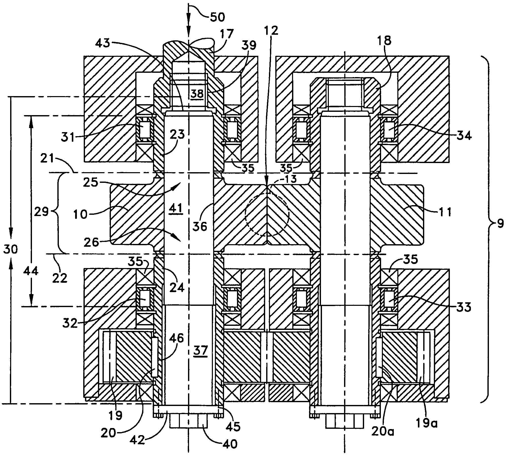
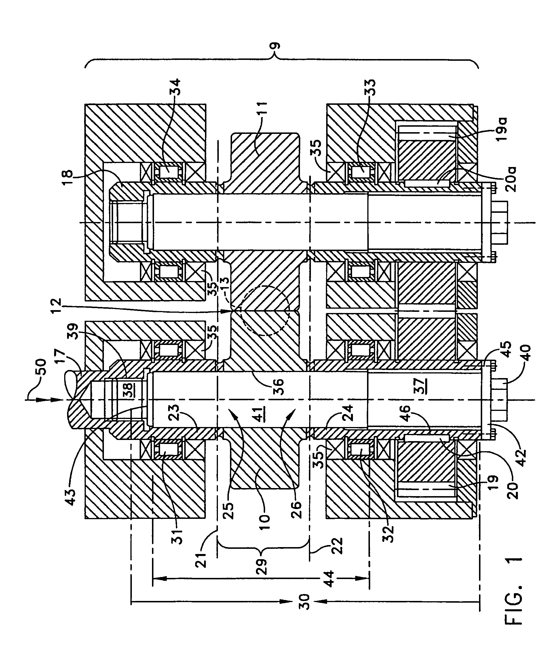
[0041]Well known in the state of the art are powder compacting machines where a vertical filler neck is mounted in a machine frame whose fill opening is accessible from the outside.

[0042]It is also well known that the filler neck opens into a vertically disposed feed hopper. A stirring device revolves in the convergent region of the hopper. A screw feeder is coupled coaxially to the stirring device. The stirring device and the screw feeder are driven via an angular gear at the top end of feed hopper. The drive is a worm motor coupled to the input end of the angular gear.

[0043]The fed-in power is conveyed by the screw feeder to the compacting plant, which is disposed under the feed hopper.

[0044]The compacting plant essentially comprises two compacting elements 10, 11. In the present case, these are two compacting rolls disposed mutually in parallel, the distance between the axes of the rolls being slightly greater than the sum of the radii of the two rolls.

[0045]This creates, below t...


PUM


Abstract

The present invention concerns a compacting machine, in which the compacting elements can be removed from the compactor housing transversely to the direction of the drive shafts.

Description

BACKGROUND OF THE INVENTION[0001]1. Field of the Invention[0002]The present invention concerns a powder compacting machine.[0003]Such a compacting machine is presumably generally known; see, for example, the prospectus “The Powder Compacting / Granulating Machine RC 100×30 for Laboratory and Production.”[0004]Although this is not intended to signify a restriction of the invention, such compacting machines according to this invention are preferably designed for small throughputs and thus for processing small batches of no more than about 2 kg.[0005]2. Description of the Prior Art[0006]A particular problem with such compacting machines designed for small-batch processing is the inevitable waste that remains in the compacting machine after the processing of the batch. In practice, the powder to be processed, settles in the compacting machine and does not pass into the usable discharge from the machine. If a different batch is to be processed in the next run, the compacting machine has to...

Claims


Application Information

Patent Timeline
IPC IPC(8): B02C4/02B30B3/04B30B3/00B30B11/16B30B11/18
CPCB30B3/04B30B11/18B30B11/16
Inventor TELLER, BERNDHUGEN, THOMAS
Owner TELLER BERND
Why Eureka
Try Eureka