
Method for induction sealing a plastic part to a composite container

a plastic part and composite container technology, applied in the direction of caps, liquid handling, and closures using stoppers, can solve the problems of difficult to obtain a broad seal between a plastic part and a composite container at high production speed, target material to heat up, and most commercially available induction sealing machines provide extremely local heating

Inactive Publication Date: 2004-04-27
SONOCO DEV INC
View PDF34 Cites 31 Cited by
  • Summary
  • Abstract
  • Description
  • Claims
  • Application Information

AI Technical Summary

Benefits of technology

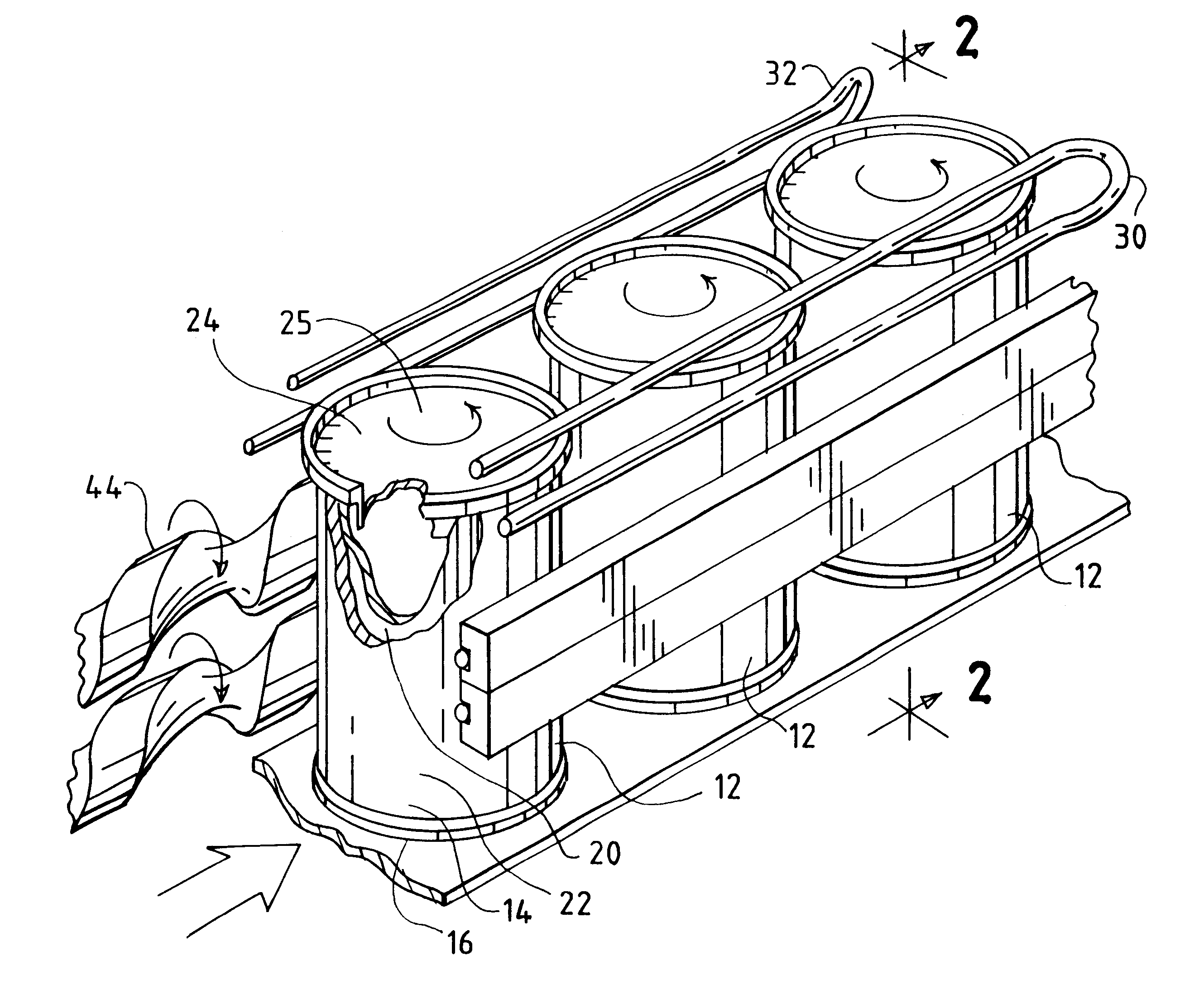
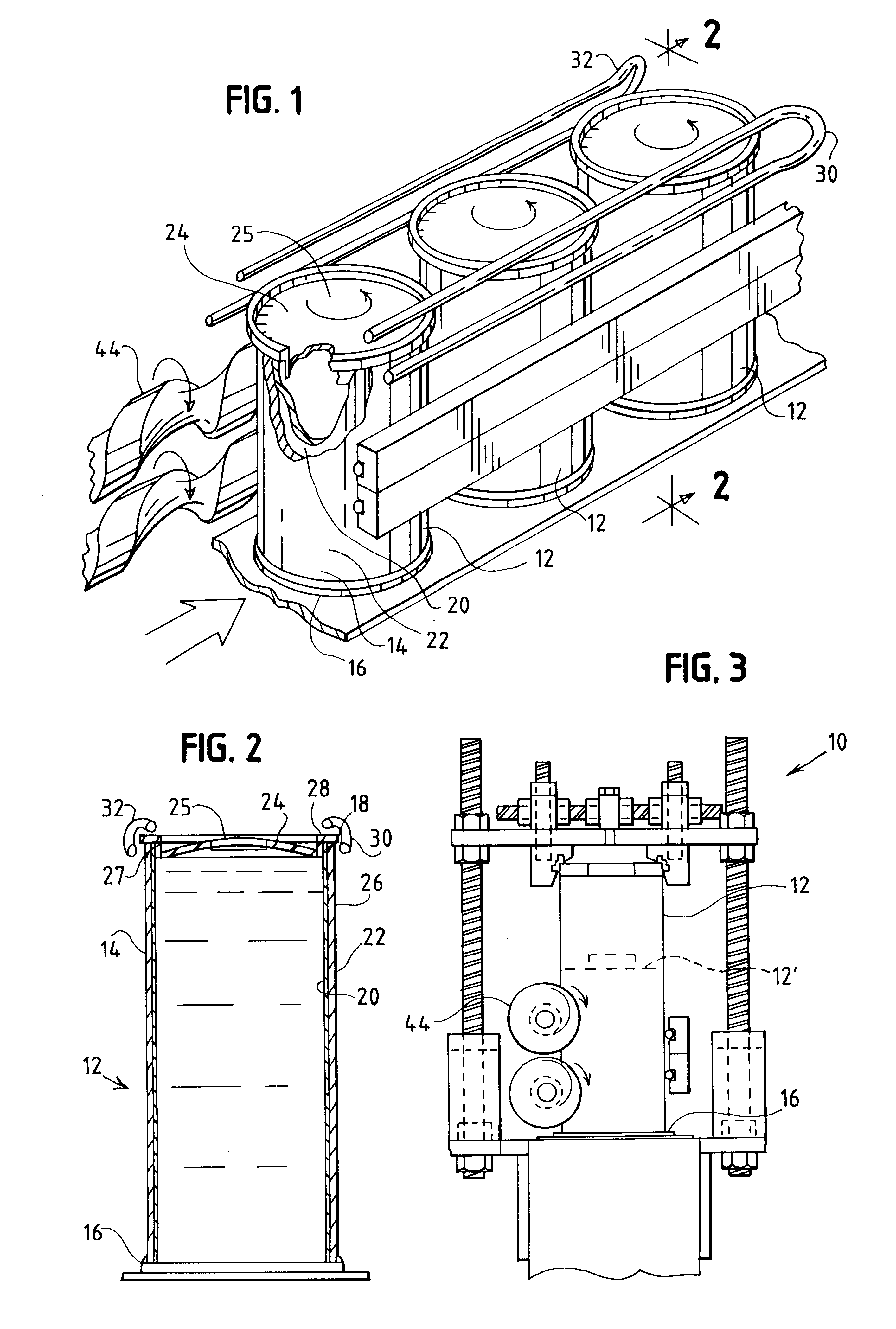
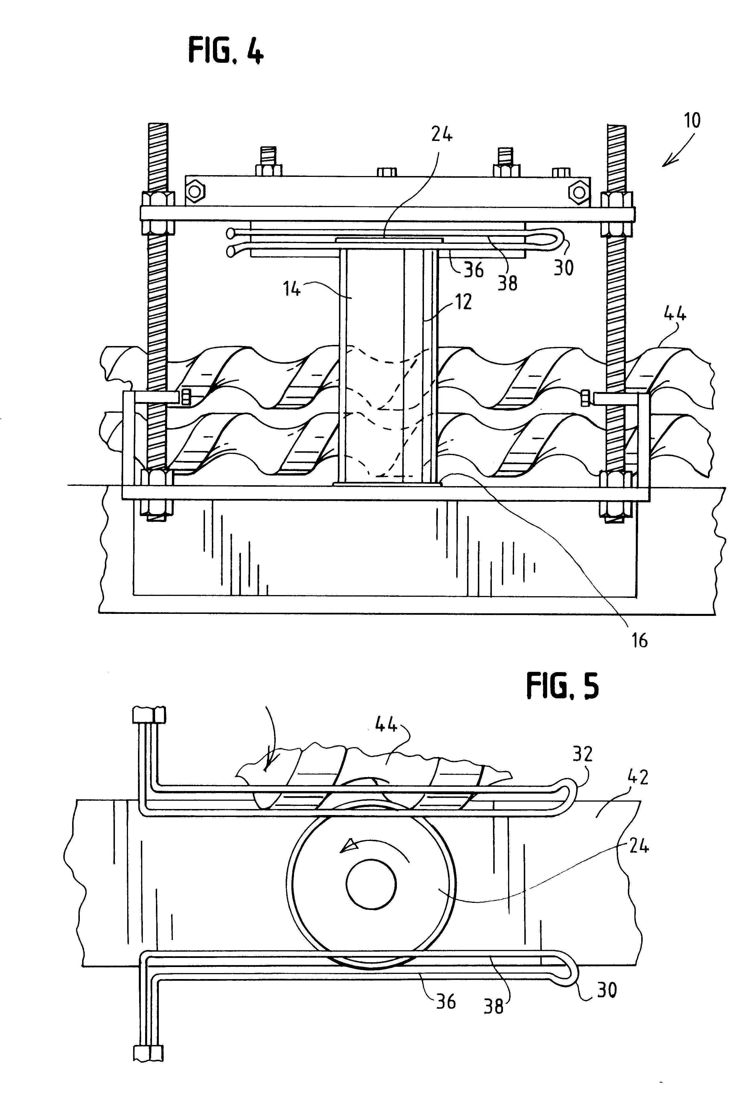
The present invention is a method and apparatus for induction sealing a plastic part to a composite container. The method involves positioning the plastic part on the container, exposing the container to a pair of electromagnetic fields generated by a pair of induction coils, and rotating the container while it is exposed to the fields. This results in a seal between the plastic part and the thermoplastic inner layer of the container. The technical effect of this invention is to provide a method for achieving a broad seal between the plastic part and the composite container at faster production speeds than conventional induction sealing processes.

Problems solved by technology

When the target material is exposed to the electromagnetic field, eddy currents are created in the target material, causing the target material to heat up because of resistance losses.
Unfortunately, most commercially available induction sealing machines provide extremely localized heating.
As a consequence, it is difficult to obtain a broad seal between a plastic part and a composite container at high production speeds.

Method used


Image

  • Method for induction sealing a plastic part to a composite container
  • Method for induction sealing a plastic part to a composite container
  • Method for induction sealing a plastic part to a composite container

Examples


Embodiment Construction

Molded polyethylene plastic lids were sealed onto composite containers using an induction sealing apparatus. The containers had a body comprising a polyfoil inner liner, a structural layer made from recycled paper, and an outer label made from paper and bearing graphics. The polyfoil inner liner included a layer of aluminum foil 0.00035 inches thick. The plastic lids were positioned onto the composite container so that they formed a friction fit with the inside of the top portion of the container body.

Normally, thin foils such as 0.00035 inch-thick aluminum foil typically used in composite containers do not heat well with low frequency generators (generators that generate frequencies lower than 450 KHz). Surprisingly, we found that excellent bonding between the thermoplastic liner and the plastic part could be achieved using generators that generate frequencies in the range of 80-200 KHz, such as the 15 KW generators manufactured by Lepel Corporation.

The containers were placed on a ...


PUM

PropertyMeasurementUnit
lengthaaaaaaaaaa
thickaaaaaaaaaa
electrically conductiveaaaaaaaaaa

Abstract

A method for induction sealing a plastic part to a composite container using a pair of linear coils electrically connected to low frequency generators. The linear coils produce overlapping electromagnetic fields on either side of the container. Rotating the container assures even heating of the polyethylene liner and plastic part. The method produces a reliable seal between the liner and plastic part and can be used at high production speeds.

Description

1. Field of the InventionThis patent relates to a method for attaching a plastic part to a composite container using induction heating. More particularly, this patent relates to a method for induction sealing a plastic part to a composite container by positioning the plastic part onto the top portion of the container and exposing the top portion of the container to electromagnetic fields generated by a pair of linear shaped coils.2. Description of the Related ArtComposite containers are commonly used to hold drink mixes, snacks and other foods. A typical composite container has a cylindrical body, a plastic or metal bottom and a plastic overcap. The container body is comprised of a polyfoil inner liner, a paperboard structural layer and a paper outer label. The polyfoil inner layer has a moisture-proof thermoplastic layer that contacts the container contents, a metallic foil layer adjacent the thermoplastic layer, and an outer paper layer. A plastic seal may be positioned under the ...

Claims


Application Information

Patent Timeline
Patent Type & Authority Patents(United States)
IPC IPC(8): B29C65/02B65B7/28B65B51/22B29C65/00B65B51/10
CPCB29C65/3656B29C66/836B29C66/72321B29C66/84123B65B7/2878B65B51/227B29C65/368B29C66/542B29C65/3644B29C66/5344B29C66/65B29C66/849B29C66/91445B29K2023/06B29K2023/12B29K2305/00B29K2305/02B29K2311/12B29L2009/003B29C65/3668B29C65/00B29C66/71B29C66/7392B29C65/787B29C66/612B29C66/8223B29C66/1222B29C66/1224B29C66/131B29L2031/717B29C66/72328B29K2705/02B29K2023/00
Inventor REA, KEITH R.BRADDOCK, CHARLES M.BOATWRIGHT, FLOYDMORROW, J. MARKLOWRY, JAMES A.
Owner SONOCO DEV INC
Learn More