Arrangement of corner reflectors for a nearly omnidirectional return

a technology of corner reflectors and omnidirectional return, which is applied in the direction of optics, instruments, and antennas, can solve the problems of cost and weight limitation, unsuitability of luneberg lenses for many applications, and general limitation, and achieves significant limitation

Inactive Publication Date: 2004-06-01
CANNING FRANCIS X
View PDF18 Cites 11 Cited by
  • Summary
  • Abstract
  • Description
  • Claims
  • Application Information

AI Technical Summary

Problems solved by technology

However, the Luneberg Lens is unsuitable for many applications for reasons such as cost and weight.
Cost and weight are also a limitation for the Van Atta Array, which generally is sensitive to the direction of incidence.
However, in prior art they generally have had a significant limitation.
This can be a significant limitation.
However, if there are certain directions where the backscattered return is weak, then for ships approaching from these directions they might not be seen from a distance and a collision might occur.
This results in a serious limitation in prior art.
The standard array of corner reflectors has a significant limitation.
However, this is not sufficient to ensure a strong retro return for all angles of incidence.
The return from two or more corner reflectors may interfere constructively or destructively.
Destructive interference can cause two returns to cancel or to nearly cancel each other, resulting in a very weak total return.
It is unlikely that destructive interference would give a very weak return for any angle of incidence.
However, this method generally produces a somewhat uniform return for all angles, which is uniformly moderate, not strong and not weak.
If their phases are approximately opposite, then they interfere destructively.
This would result in constructive interference.
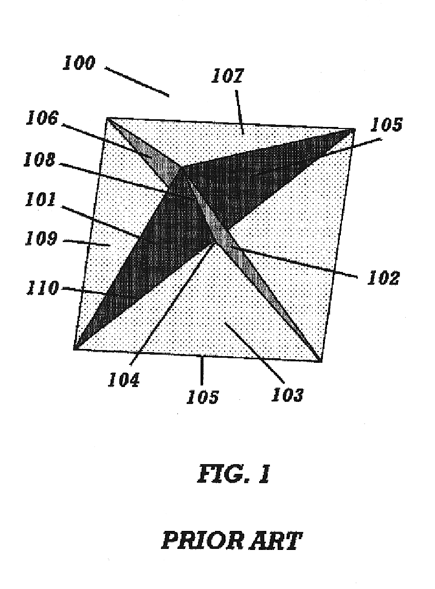
A limitation of this array is that as one looks at it substantially horizontally from various azimuthal directions, there are six such directions in which there is no corner with its interior visible.
This generally results in a larger retro return from that one corner.
However, for small changes in the incident direction the dihedral return may not be strong.

Method used


Image

  • Arrangement of corner reflectors for a nearly omnidirectional return
  • Arrangement of corner reflectors for a nearly omnidirectional return
  • Arrangement of corner reflectors for a nearly omnidirectional return

Examples


Embodiment Construction

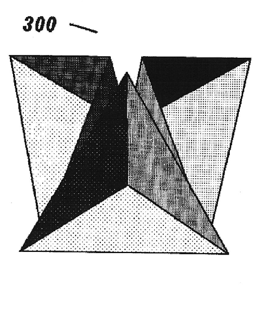
FIG. 7 shows the radar cross section in the retro direction for four different arrangements of corners (FIGS. 6 through 9 all show the results of approximate numerical computations). The corners used for FIG. 7 all have sides formed from a ninety degree section of a circle. Two edges of each side are straight and are five wavelengths long. The third edge is a circular arc of radius five wavelengths. The curve 701 gives the radar cross section for the standard array of such corners in the hold water orientation.

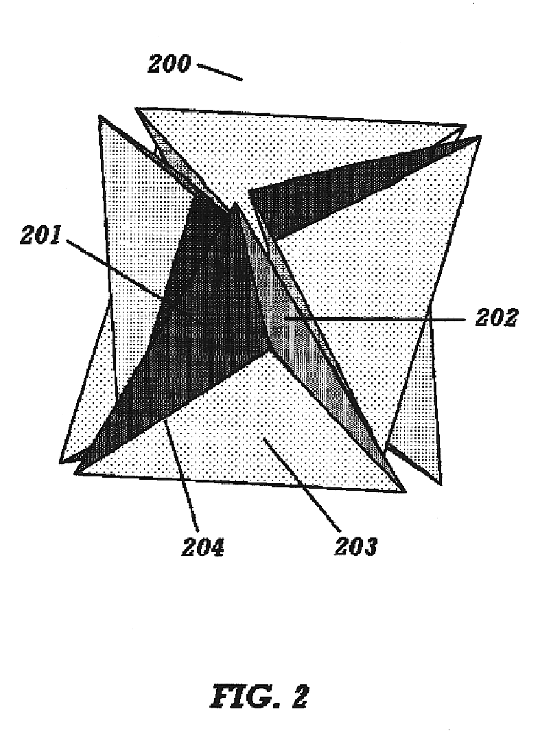
The radar cross section for a first preferred embodiment is shown as the curve 702 in FIG. 7. An opening rotation of eight degrees is used. The three upper corners are displaced vertically by two and a tenth wavelengths above the three lower corners. In addition, the three lower corners are also each displaced radially by half a wavelength towards each other. The three upper corners are also each displaced radially by half a wavelength towards each other. As a result, they int...


PUM


Abstract

An array of corner reflectors is used to provide a retro-reflector for a large range of incident angles. A novel orientation of the individual corner reflectors is used. This allows the interior of a first corner to remain visible while the interior of a second corner becomes visible. This may be done while maintaining a phase coherence between the contributions of the first and second corner reflectors. Phase coherence ensures constructive interference among the returns from the first and second corner reflectors. Coherence is achieved by an arrangement which places the interior vertices of the corner reflectors close to each other. One such arrangement also places the peak return from one corner reflector acting as a dihedral between the locations of the dihedral and trihedral returns of a second corner reflector. This arrangement results in a substantially uniform and strong retro-return. Phase coherence may be maintained over a desired range of elevation angles.

Description

1. Field of the InventionRetro reflectors for electromagnetic waves, acoustic waves, and other wave phenomena have been known since the Fessenden patent (1,384,014) in 1921. These devices reflect the wave energy preferentially in the direction back toward the source. This creates a much stronger reflection of energy back toward the source than would occur if the reflection were to be equally strong in all directions.2. Description of the Related ArtA retro reflector is a device which generally produces a strong return in the direction of the source, while the strength of this return may depend on the orientation of the reflector. The Luneberg Lens is completely insensitive to the direction of incidence of the waves. This is often a desirable property. However, the Luneberg Lens is unsuitable for many applications for reasons such as cost and weight. Cost and weight are also a limitation for the Van Atta Array, which generally is sensitive to the direction of incidence.An alternative...

Claims


Application Information

Patent Timeline
Patent Type & Authority Patents(United States)
IPC IPC(8): G02B5/12
CPCG02B5/12
Inventor CANNING, FRANCIS X.
Owner CANNING FRANCIS X
Why Eureka
Try Eureka