
Combined directional and mobile interleaved wireless mesh network

a wireless mesh network and interleaved technology, applied in the field of wireless mesh networks, can solve the problems of complex and difficult to deal with the mesh network where the channel change from hop to hop is complicated, significant bandwidth limitation, etc., and achieve the effect of improving the performance of the highest priority packet stream

Inactive Publication Date: 2007-08-09
SECOND SIGHT MEDICAL PRODS +1
View PDF42 Cites 60 Cited by
  • Summary
  • Abstract
  • Description
  • Claims
  • Application Information

AI Technical Summary

Benefits of technology

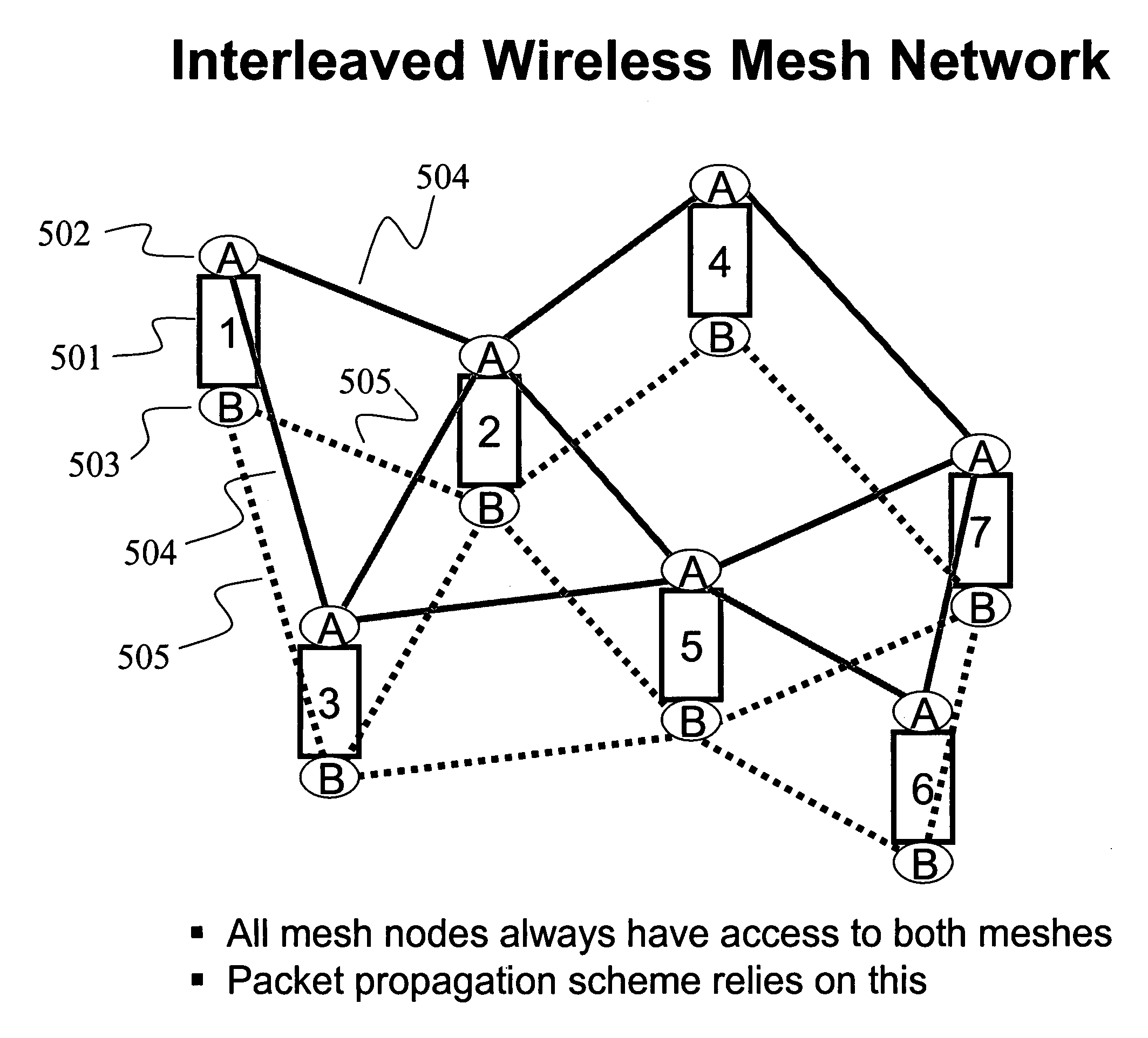
"This patent describes an interleaved mesh network that uses multiple radios on each node to create multiple simultaneous networks. This improves performance by allowing packets to be relayed through the mesh using multiple paths, resulting in faster transmission times and better performance regardless of traffic loading. The use of directional antennas and seamless integration with mobile mesh nodes also allows for increased performance in public safety applications. The invention provides a more robust mesh architecture, increased performance over traditional mobile mesh with single radio relay, and support for mobile and fixed mesh nodes with multiple radios. The use of multiple radios and antennas operating on the same channel or facing in different directions on the same mesh node reduces the need for channels and allows for coordinated transmission and reception to eliminate interference. Overall, the invention provides higher performance for video broadcast distribution and video multicast for surveillance applications."

Problems solved by technology

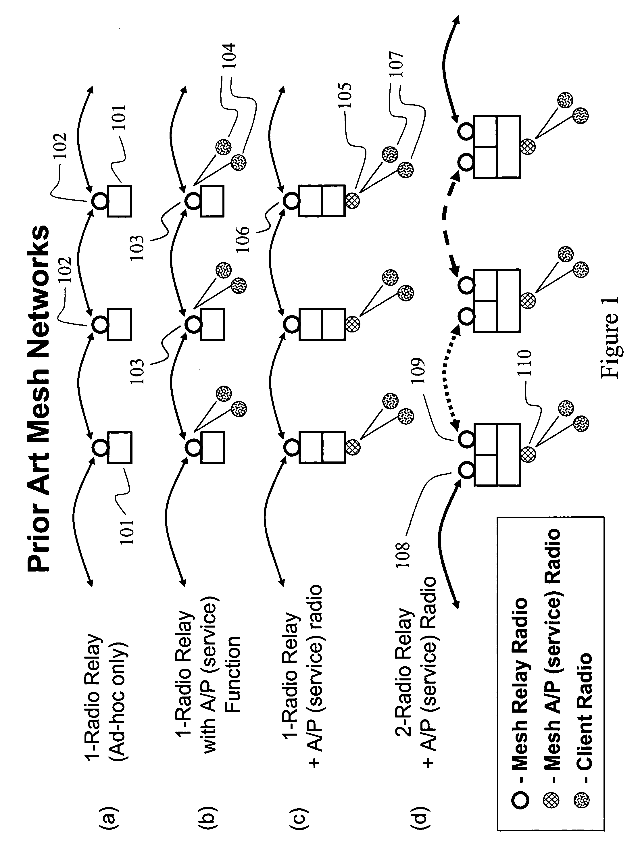
This causes a significant bandwidth limitation since a single radio cannot send and receive at the same time.
The architecture of FIG. 1(b) suffers from performance limitations since the single radio must not only relay packets, but also service numerous client radios 104 at each node.
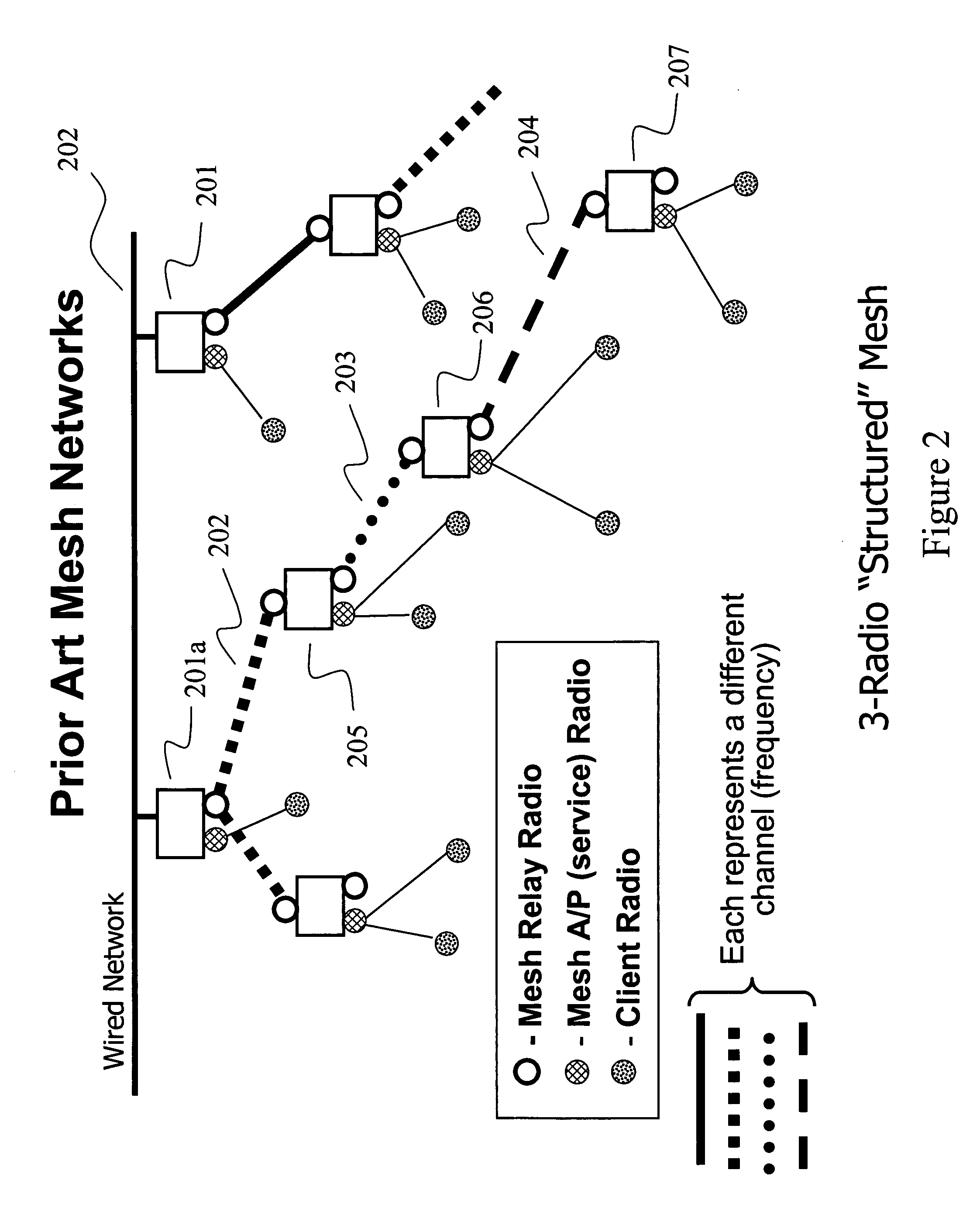
In this type of mesh network, the mesh control software on each node has a significant challenge in assigning the various available channels throughout the mesh such that interference effects are minimized, and the mesh functions properly.
Either way, having a mesh network where channels change from hop to hop is complicated and difficult to deal with.
In the case of a public safety mesh with mobile nodes (for vehicles and individual First Responders on foot), a further problem arises with this form of mesh.
For instance, if a group of first responders each carrying a mesh node becomes isolated from the backhaul connection to the server (Command and Control), the tree-like structure of FIG. 2 may become compromised since there is no longer a defined root for the tree.
i>e). Also, when connections between nodes must change because of a node failure, temporary disturbances to the mesh (moving obstacles or radar interference), node movement, or QOS considerations, there can be a ripple effect of changing channels causing even greater c
However, the solution does not integrate any additional functionality beyond what is shown in FIG. 4, and from a performance standpoint, each of the two individual mesh networks embodied here will have the performance restrictions of other prior art mesh architectures constructed according to FIG. 1(c).
While some mesh vendors claim to have installed mesh networks in hundreds of cities, all but a few of these are suburban towns, not large cities with tall buildings.
In fact, none of the mesh systems offered today have been designed to handle the problems encountered in the depths of larger cities where high rise buildings create a “concrete canyon” effect.
When today's mesh nodes are deployed in such situations, much of the energy radiated from their omni-directional antennas is reflected and / or wasted.
Other factors involved in mesh node and mesh architecture design involve both the transmit power and cost of radio cards.
Frequencies in the 700 MHz to 900 MHz range have great penetration and range capabilities, but are prone to adjacent channel interference.

Method used


Image

  • Combined directional and mobile interleaved wireless mesh network
  • Combined directional and mobile interleaved wireless mesh network
  • Combined directional and mobile interleaved wireless mesh network

Examples


Embodiment Construction

[0070] The invention is illustrated by way of example and not by way of limitation in the figures of the accompanying drawings in which like references indicate similar elements. References to embodiments in this disclosure are not necessarily to the same embodiment, and such references mean at least one. While specific implementations are discussed, it is understood that this is done for illustrative purposes only. A person skilled in the relevant art will recognize that other components and configurations may be used without departing from the scope and spirit of the invention.

[0071] In the following description, numerous specific details are set forth to provide a thorough description of the invention. However, it will be apparent to those skilled in the art that the invention may be practiced without these specific details. In other instances, well-known features have not been described in detail so as not to obscure the invention.

[0072] One of the key components of the presen...


PUM


Abstract

A combined fixed directional and mobile omnidirectional interleaved wireless mesh network is described where the fixed mesh nodes have directional antennas facing in horizontally orthogonal directions. The antennas can be focused to have a horizontal beam width of less than ninety degrees in order to achieve greater strength of signal and radiation. Each directional node can have multiple radios that communicate on separate channels, such that packets propagated through the mesh network can utilize any channel to enter or leave a particular node. The combined network also includes mobile nodes that utilize multiple radios, each connected to an omnidirectional antenna and operating on a different channel. The mobile nodes can maintain constant communication with the directional nodes as they move between various quadrants covered by the directional nodes. The mobile nodes can also maintain connections to each other even during the loss of communication with the fixed directional nodes.

Description

CLAIM OF PRIORITY [0001] This application claims the benefit and priority of U.S. Provisional Application Ser. No. 60 / 756,794, filed on Jan. 5, 2006, and entitled “DIRECTIONAL AND INTERLEAVED WIRELESS MESH NETWORKS,” commonly assigned with the present application and incorporated herein by reference. CROSS REFERENCES TO RELATED APPLICATIONS [0002] This application is related to and cross references the following U.S. Patent Applications, which are incorporated herein by reference: [0003] U.S. patent application Ser. No. 11 / 507,921 entitled “INTERLEAVED AND DIRECTIONAL WIRELESS MESH NETWORK,” by Robert Osann, Jr., filed on Aug. 22, 2006, Attorney Docket No. OSAN-01003US0. [0004] U.S. patent application Ser. No. 11 / 503,036 entitled “INTERLEAVED WIRELESS MESH NETWORK,” by Robert Osann, Jr., filed on Aug. 11, 2006, Attorney Docket No. OSAN-01004US0. [0005] U.S. patent application Ser. No. 11 / 516,995 entitled “SYNCHRONIZED WIRELESS MESH NETWORK,” by Robert Osann, Jr., filed on Sep. 7, 20...

Claims


Application Information

Patent Timeline
Patent Type & Authority Applications(United States)
IPC IPC(8): H04L12/56
CPCH01Q25/00H04W92/20H04W84/18H04W40/246
Inventor OSANN, ROBERT JR.
Owner SECOND SIGHT MEDICAL PRODS
Learn More