
Method for multicast frame transmission and duplicated multicast frame detection

a multicast frame and detection method technology, applied in the field of multicast/broadcast procedure, can solve the problems of short communication distance, limited radio resources, and difficulty in confirming whether a terminal is registered to a specific multicast group, i.e., a destination terminal, so as to ensure the reliability of multicast transmission and expand service coverage

Active Publication Date: 2011-08-18
LG ELECTRONICS INC
View PDF18 Cites 60 Cited by
  • Summary
  • Abstract
  • Description
  • Claims
  • Application Information

AI Technical Summary

Benefits of technology

[0023]According to the present invention, a wireless local area network (WLAN) can not only expand service coverage but also ensure reliability of multicast transmission.

Problems solved by technology

Disadvantageously, however, the IEEE 802.11a has a shorter communication distance than the IEEE 802.11b.
This is caused by the fact that a channel using the band of 6 GHz or lower is in use also by other wireless communication systems, and thus available radio resources are limited.
In multicast transmission, it is difficult to confirm whether a terminal registered to a specific multicast group, i.e., a destination terminal, has successfully received all pieces of data provided from a source terminal.
Therefore, a current multicast service does not guarantee that the destination terminal can completely and reliably receive data to be multicast.
However, the use of a low modulation scheme results in deterioration of a data transfer rate, which may impair improvement of a data throughput of a WLAN system.

Method used


Image

  • Method for multicast frame transmission and duplicated multicast frame detection
  • Method for multicast frame transmission and duplicated multicast frame detection
  • Method for multicast frame transmission and duplicated multicast frame detection

Examples


Embodiment Construction

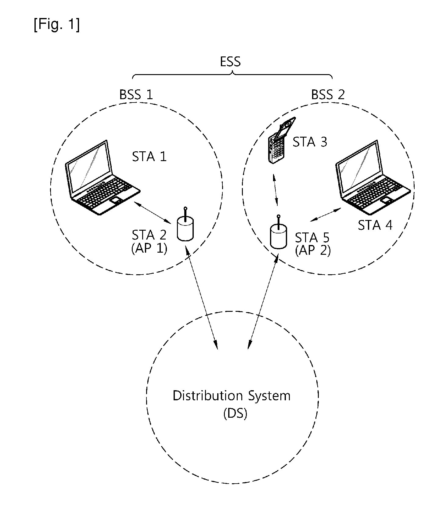
[0033]Embodiments of the present invention described below can effectively apply to a multicast procedure of a very high throughput (VHT) wireless local area network (WLAN) system operating in a band of 60 GHz. However, the present invention is not limited thereto. For example, the embodiments of the present invention can also equally apply to a VHT WLAN system operating in a band of 6 GHz or lower.

[0034]In addition, in multicast, a target address or a destination address of a transmit (Tx) frame is specified as a multicast group address. Broadcast is special multicast in which the multicast group address specifies all terminals. Therefore, when simply referred to as ‘multicast’ in the following description, it will be interpreted that ‘broadcast’ is also included unless it is not allowed by nature.

[0035]FIG. 1 is a schematic view showing an exemplary structure of a VHT WLAN system according to an embodiment of the present invention.

[0036]Referring to FIG. 1, a WLAN system such as t...


PUM


Abstract

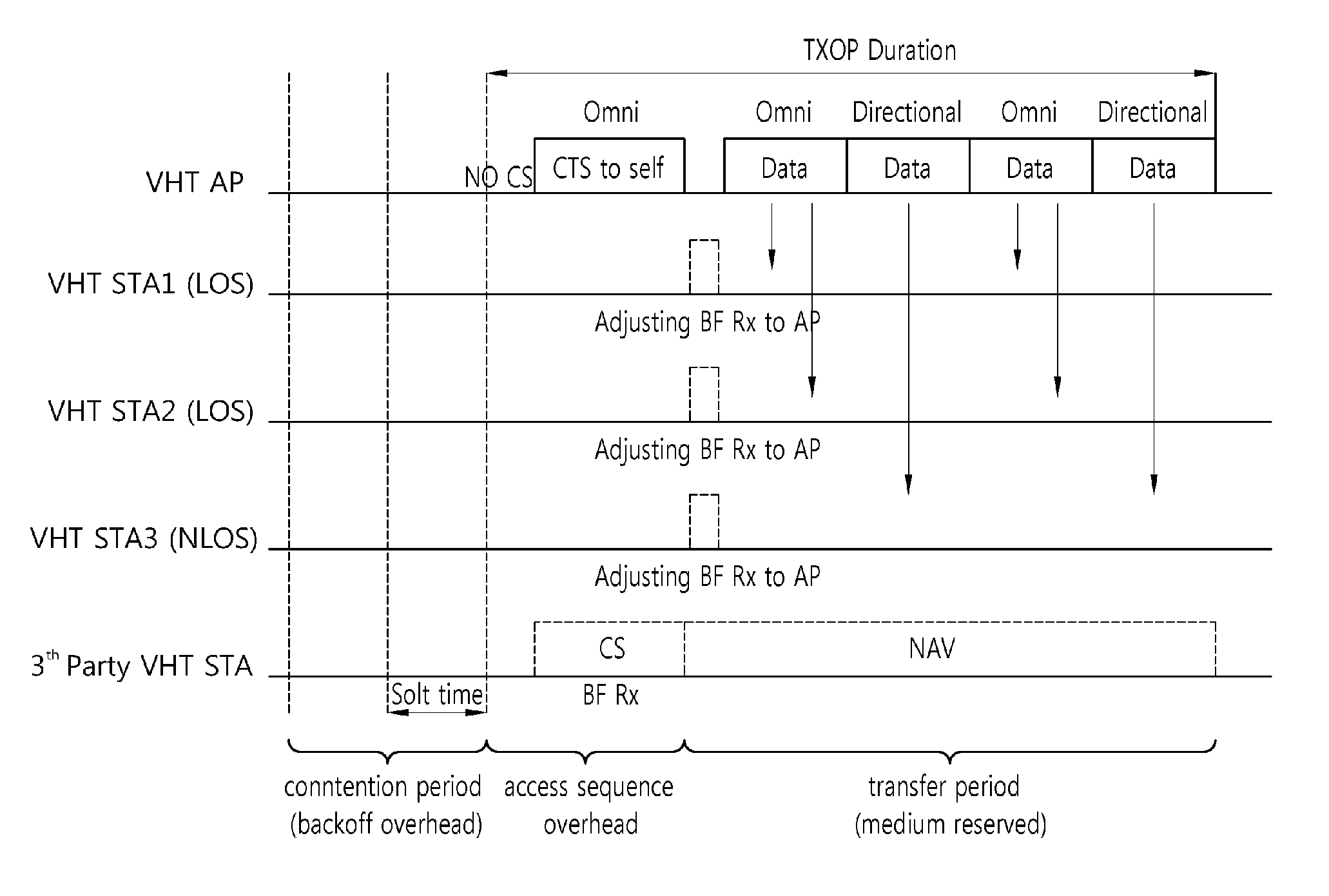
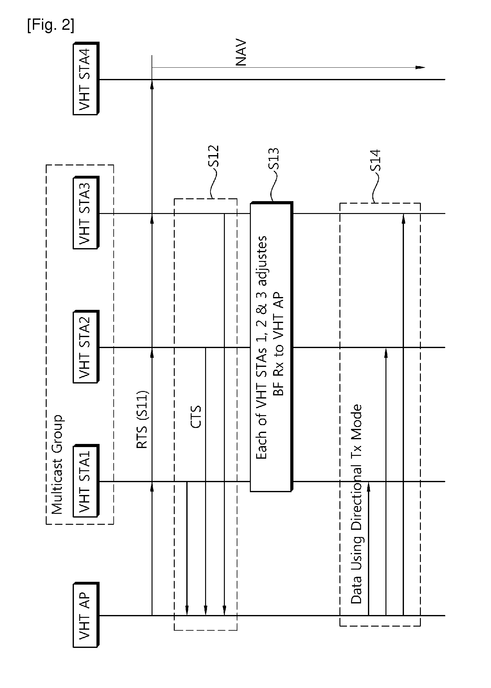
A method and apparatus of transmitting a multicast frame in a wireless communication system is provided. The method comprises transmitting a request to send (RTS) frame to stations (STAs) included in a multicast group by using an omni-directional antenna, and receiving a clear to send (CTS) frame transmitted by the STAs included in the multicast group in response to the RTS frame, and transmitting the multicast frame to the STAs included in the multicast group by using a directional antenna.

Description

TECHNICAL FIELD[0001]The present invention relates to a wireless local area network (WLAN), and more particularly, to a multicast / broadcast procedure in a very high throughput (VHT) WLAN system.BACKGROUND ART[0002]With the advancement of information communication technologies, various wireless communication technologies have recently been developed. Among the wireless communication technologies, a wireless local area network (WLAN) is a technology whereby Internet access is possible in a wireless fashion in homes or businesses or in a region providing a specific service by using a portable terminal such as a personal digital assistant (PDA), a laptop computer, a portable multimedia player (PMP), etc.[0003]Ever since the institute of electrical and electronics engineers (IEEE) 802, i.e., a standardization organization for WLAN technologies, was established in February 1980, many standardization works have been conducted. In the initial WLAN technology, a frequency of 2.4 GHz was used...

Claims


Application Information

Patent Timeline
IPC IPC(8): H04W4/06
CPCH04W74/0816H04W4/06H04W16/28H04W84/12
Inventor SEOK, YONG HO
Owner LG ELECTRONICS INC
Learn More