Injection apparatus

a technology of injection apparatus and injection chamber, which is applied in the direction of presses, applications, manufacturing tools, etc., can solve the problems of increasing the cost of injection apparatus, emergence of torque loss, and requiring a longer time for building-in work,

Inactive Publication Date: 2004-06-29
SUMITOMO HEAVY IND LTD
View PDF22 Cites 9 Cited by
  • Summary
  • Abstract
  • Description
  • Claims
  • Application Information

AI Technical Summary

Benefits of technology

The present invention further provides an injection apparatus which comprises an injection frame; a cylinder member attached to the injection frame; an injection member disposed within the cylinder member such that the same can rotate and can advance and retreat; a rotary slide member attached to the injection member; a stator attached to the injection frame, and a rotor supported radially inward of the stator to be rotatable relative to the stator; and a rotational-speed detecting section for detecting a rotational speed of the rotor.
In this case, the rotor comprises the cylindrical member and the magnet, and can transmit generated rotation directly to the rotary slide member, thereby eliminating the need for a transmission mechanism, which is composed of an output gear, a counter drive gear, a counter driven gear, a rotary member, etc., and preventing generation of noise, which would otherwise result from engagement of gears and other members. Thus, the number of components can be reduced; emergence of torque loss can be prevented; and the cost of the injection apparatus can be reduced. Further, since a space for disposition of the first drive section can be reduced, the injection apparatus can be reduced in size accordingly.

Problems solved by technology

Further, a large number of components are employed, resulting in emergence of torque loss and an increase in the cost of the injection apparatus.
Therefore, when meshing engagement cannot be established properly at the spline portion, the building-in work requires a longer time, which deteriorates easiness of assembly, maintenance, etc.

Method used


Image

  • Injection apparatus
  • Injection apparatus
  • Injection apparatus

Examples


first embodiment

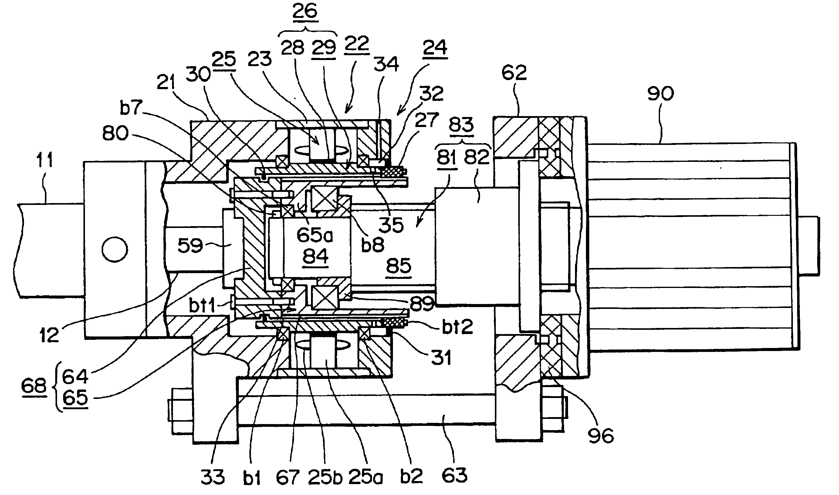
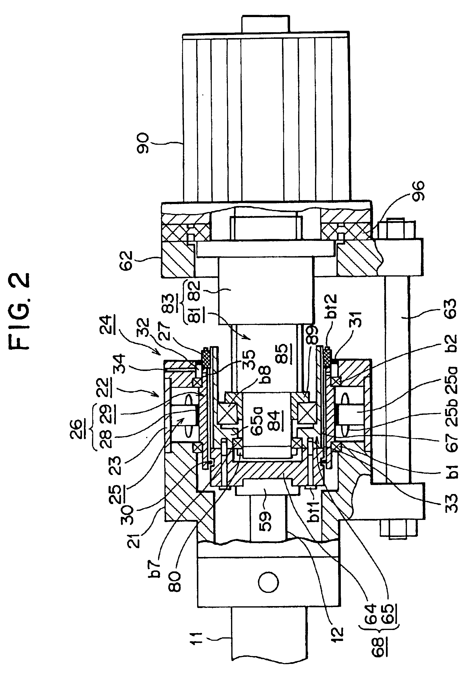
FIG. 2 conceptually shows an injection apparatus according to the present invention.

In FIG. 2, reference numeral 11 denotes a heating cylinder, which serves as a cylinder member; reference numeral 12 denotes a screw, which serves as an injection member, disposed within the heating cylinder 11 such that it can rotate and can advance and retreat (move leftward and rightward in FIG. 2); an unillustrated injection nozzle is attached to the front end (left-hand end in FIG. 2) of the heating cylinder 11; and a nozzle hole is formed in the injection nozzle.

The screw 12 includes a screw body and an unillustrated screw head attached to the front end of the screw body. An unillustrated flight is spirally formed on the outer circumferential surface of the screw body, thereby forming a spiral groove.

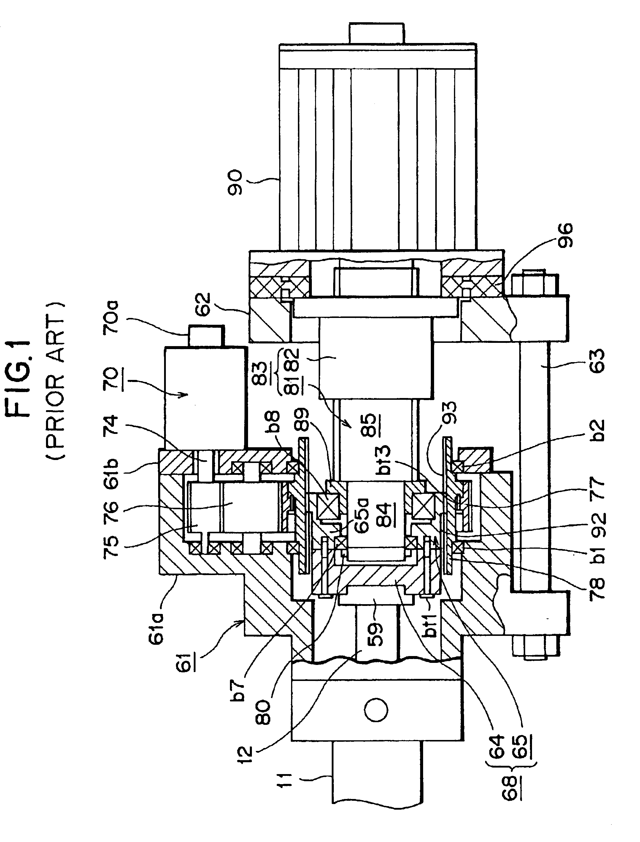
The rear end (right-hand end in FIG. 1) of the heating cylinder 11 is attached to a front injection support 21, which serves as a front support member. A rear injection support 62, which serves as a...

second embodiment

Moreover, even when the arrangement of the metering motor 22 and the injection motor 90 is changed in such a manner that the injection motor 90 is attached to the injection support 21, rotational speed of the injection motor 90 can be detected by use of gears, an output sensor, etc., as in the


PUM

PropertyMeasurementUnit
rotational-speedaaaaaaaaaa
rotational speedaaaaaaaaaa
speedaaaaaaaaaa

Abstract

An injection apparatus includes an injection frame; a cylinder member attached to the injection frame; an injection member disposed within the cylinder member such that the same can rotate and can advance and retreat; a rotary slide member attached to the injection member; a stator attached to the injection frame, and a rotor disposed radially inward of the stator to be rotatable relative to the stator. The rotor includes a hollow, cylindrical member disposed radially outward of the rotary slide member and movably relative to the rotary slide member, and a magnet attached to the cylindrical member. In this case, the rotor has a cylindrical member and a magnet and can transmit generated rotation directly to the rotary slide member. Therefore, a transmission mechanism which consists of an output gear, a counter drive gear, a counter driven gear, a rotary member, etc. becomes unnecessary; and generation of noise due to meshing engagement of gears and other components can be prevented. Accordingly, the number of components can be reduced, generation of torque loss can be prevented, and cost of the injection apparatus can be reduced.

Description

1. Field of the InventionThe present invention relates to an injection apparatus.2. Description of the Related ArtConventionally, in an injection molding machine, a screw is disposed within a heating cylinder of an injection apparatus such that it can rotate and can advance and retreat. By operating a drive mechanism, the screw can be rotated, and can be advanced and retreated. In a metering process, the screw is rotated, whereby a resin which is supplied from a hopper into the heating cylinder is melted through application of heat and transferred forward, and the molten resin is stored in a space located ahead of a screw head attached to the front end of the screw. In an injection process, the screw is caused to advance, whereby the molten resin, which is stored in the space located ahead of the screw head, is injected from an injection nozzle into the cavity of a mold apparatus so as to fill the cavity.FIG. 1 is a conceptual view of a conventional injection apparatus.In FIG. 1, re...

Claims


Application Information

Patent Timeline
Patent Type & Authority Patents(United States)
IPC IPC(8): B29C45/50B29C45/83B29C45/46
CPCB29C45/5008B29C45/83B29C2045/5024B29C2045/5032B29C2045/504B29C2045/5056B29C45/50
Inventor NISHIO, OKITO
Owner SUMITOMO HEAVY IND LTD
Why Eureka
Try Eureka