Cranial flap fixation device

a fixation device and cranial flap technology, applied in the field of fasteners, can solve the problems of dangerous movement of the bone flap against the brain, increased infection risk of drilling procedure, and unstable sutures,

Inactive Publication Date: 2004-06-29
MEDTRONIC INC
View PDF10 Cites 97 Cited by
  • Summary
  • Abstract
  • Description
  • Claims
  • Application Information

AI Technical Summary

Problems solved by technology

However, this procedure may be time consuming in that numerous holes must be drilled and, additionally, the drilling procedure may increases a risk of infection.
At the same time, sutures have been known to become unstable and even to break which can also lead to dangerous movements of the bone flap against the brain.
Furthermore, suture materials may leave irregularities in the skin surface and may fail to align the bone plate in a substantially planar fashion relative to the surface of the cranium.
Such a device may still be prone to movement of the fixation device such as "backing out" or loosening of the cap and the base.
The fixation device of the present invention may further reduce a potential of over torquing the nut, thereby attenuating a possibility that the nut or bolt will be stripped or otherwise damaged.

Method used


Image

  • Cranial flap fixation device
  • Cranial flap fixation device
  • Cranial flap fixation device

Examples


Embodiment Construction

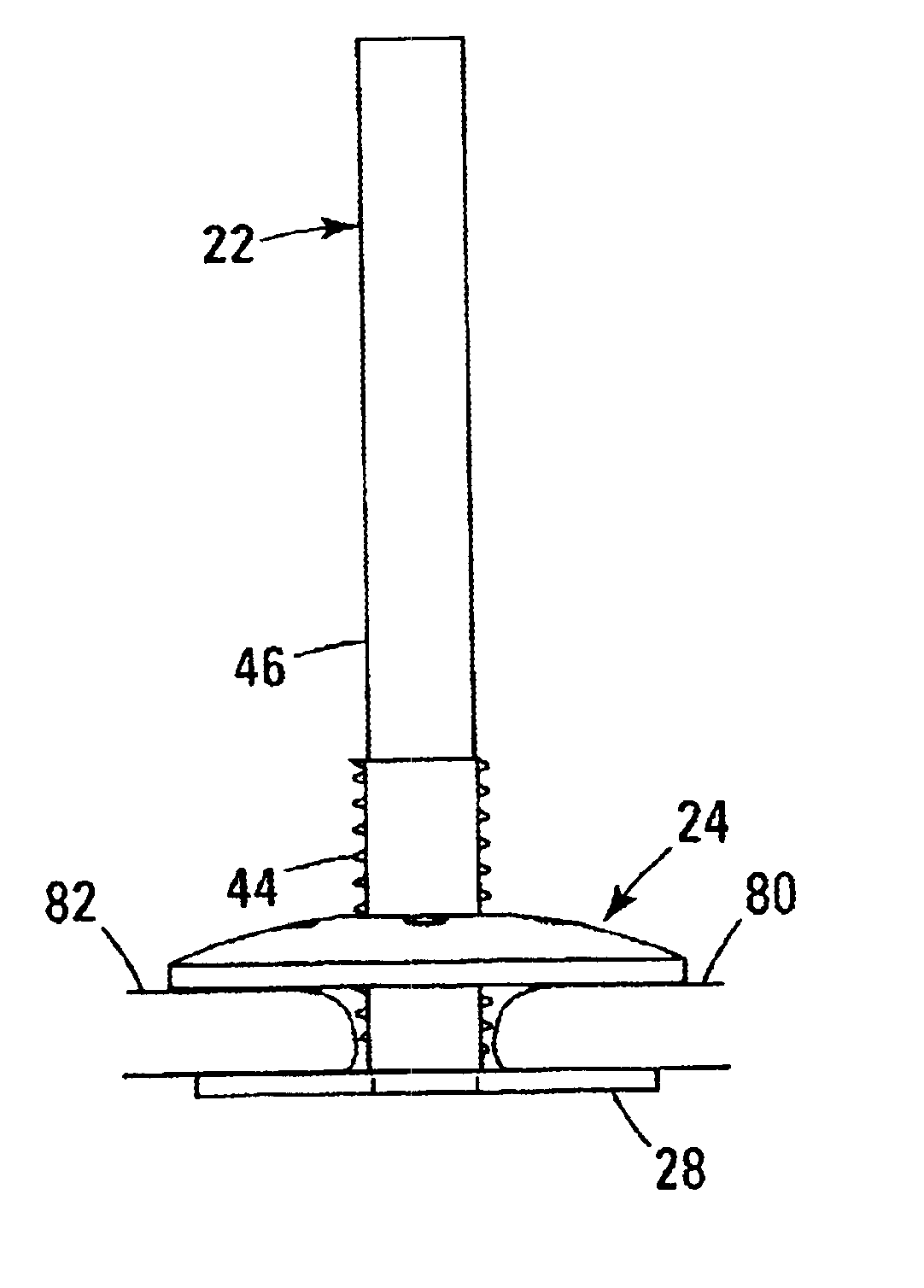
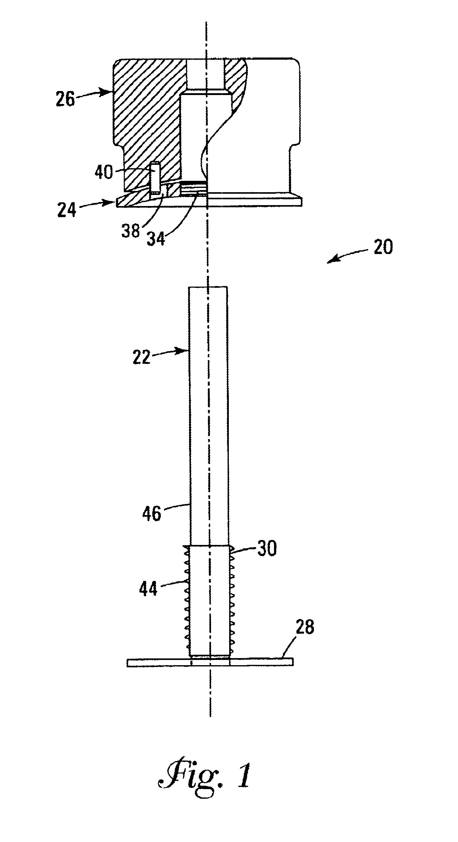
With reference to FIG. 1, the fixation system 20 of the present invention comprises an inner member 22, an outer member 24, and a driving tool 26 for engagement with the outer member 24. The inner member 22 comprises a head 28 and a shaft 30, and the outer member 24 preferably comprises a nut for being secured onto the shaft 30.

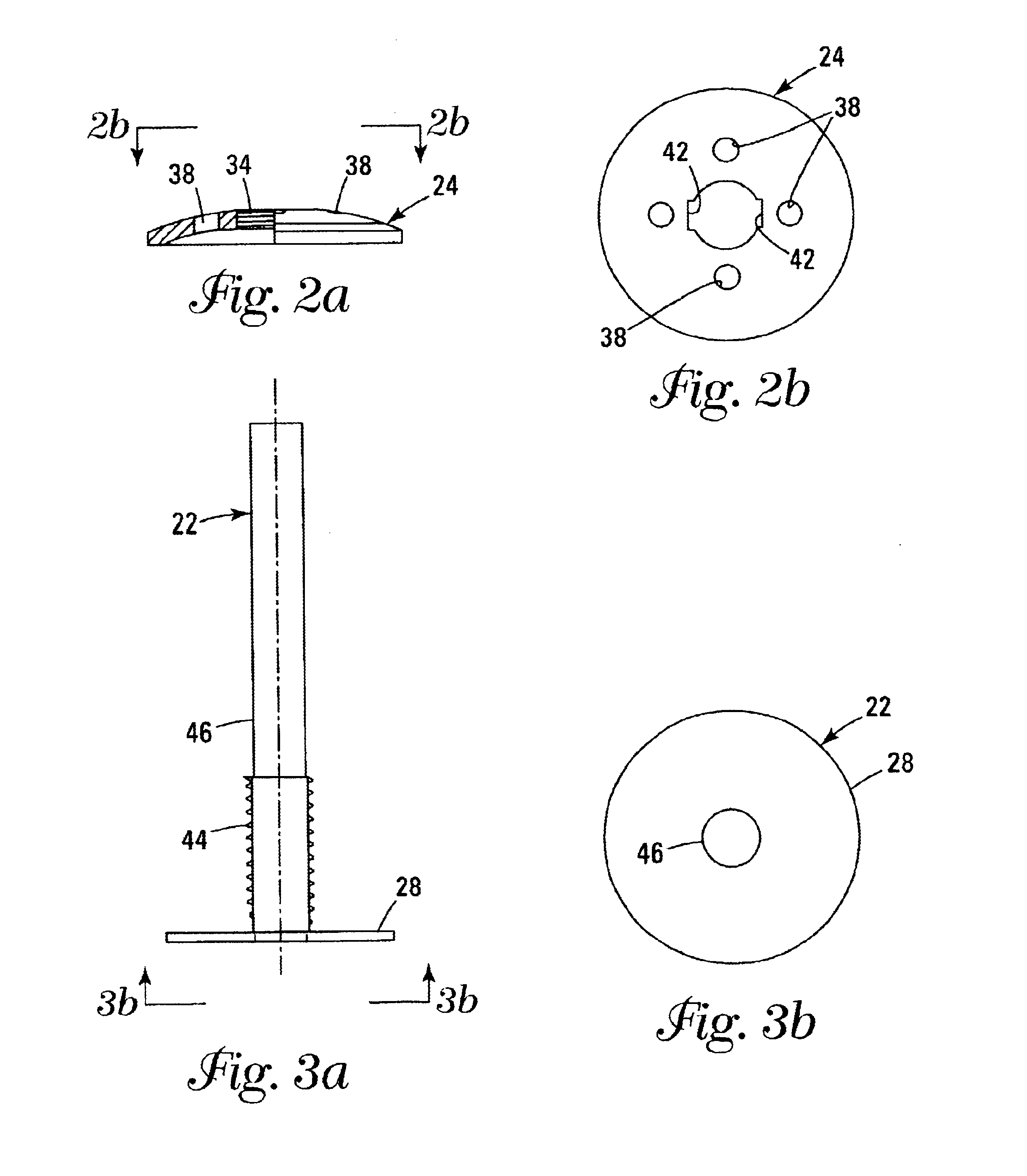
FIG. 2a illustrates a partial cross-sectional view of the outer member 24, and FIG. 2b illustrates a top planar view of the outer member 24. FIG. 3a illustrates a side-elevation view of the inner member 22, and FIG. 3b illustrates a top planar view of the inner member 22. FIG. 4a shows the outer member 24 and the driving tool 26 secured onto the inner member 22, and FIG. 4b is an exploded view of the elements of FIG. 4a.

The outer member 24 comprises a threaded aperture 34 for accommodating the shaft 30 of the inner member 22, and further comprises at least one additional aperture or notch for accommodating the driving tool 26. In the presently preferred embod...


PUM


Abstract

A cranial flap fixation device utilizing a piece design comprising an inner member and an outer member. The inner member includes a head and a shaft and the outer member comprises a nut for securing onto the shaft. A driving tool may be engaged with the inner member for secure engagement with the outer member. The present invention is also a cranial flap fixation system comprising three pieces, a nut, a bolt and a lock washer. The bolt having a threaded portion head for receipt into the nut and lock washer assembly, and the bolt also having an extra wide head portion for secure engagement inside the patient's cranium. The bolt is designed for use with a variety of bone structures since it is designed having an adjustable length so that the surgeon can cut the bolt after tightening onto the nut and lock washer assembly. A driving tool may be utilized to secure the cranial flap fixation system.

Description

1. Field of the InventionThe present invention relates generally to a fastener for securing a bone flap to surrounding bone and, more particularly, to a fastener for securing a bone flap to the cranium.2. Description of Related ArtA craniotomy is a procedure wherein a portion of the cranial vault is surgically removed to provide access by the surgeon to the inside of the head and brain. Generally, to perform the craniotomy several burr holes are drilled through the skull and then the holes are connected using an osteotomy saw to cut the skull along a line of separation connecting the adjoining burr holes. Typically, the number and position of the burr holes will vary depending on the size and shape of the bone flap to be removed. For example, if one desired to remove a triangularly shaped bone flap then it may be practical to drill three burr holes to form a triangle and then use the osteotomy saw to connect the corners of the triangle for removal of the bone flap. Once the cuts hav...

Claims


Application Information

Patent Timeline
Patent Type & Authority Patents(United States)
IPC IPC(8): A61B17/68A61B17/88
CPCA61B17/688Y10S606/907
Inventor AMIS, JAMES PETER
Owner MEDTRONIC INC
Why Eureka
Try Eureka