
Electric motor, in particular for raising and lowering disks in motor vehicles

a technology of electric motors and motor vehicles, applied in the field of electric motors, can solve the problems of cumbersome form and high cos

Inactive Publication Date: 2004-07-06
ROBERT BOSCH GMBH
View PDF19 Cites 42 Cited by
  • Summary
  • Abstract
  • Description
  • Claims
  • Application Information

AI Technical Summary

Problems solved by technology

This form is both cumbersome and expensive both from a manufacturing and an assembly perspective, in particular when Hall sensors need to be located in the area of the armature shaft for monitoring a transmission position.

Method used


Image

  • Electric motor, in particular for raising and lowering disks in motor vehicles
  • Electric motor, in particular for raising and lowering disks in motor vehicles
  • Electric motor, in particular for raising and lowering disks in motor vehicles

Examples


Embodiment Construction

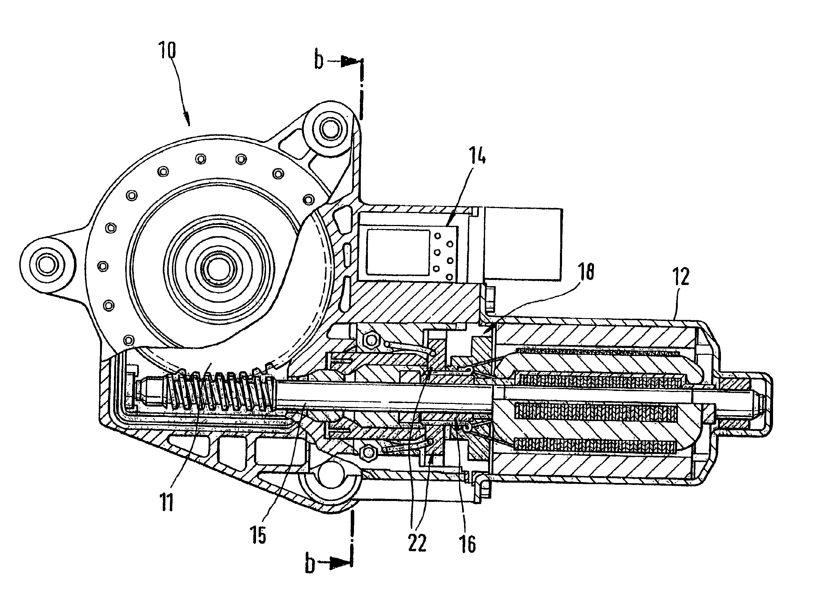
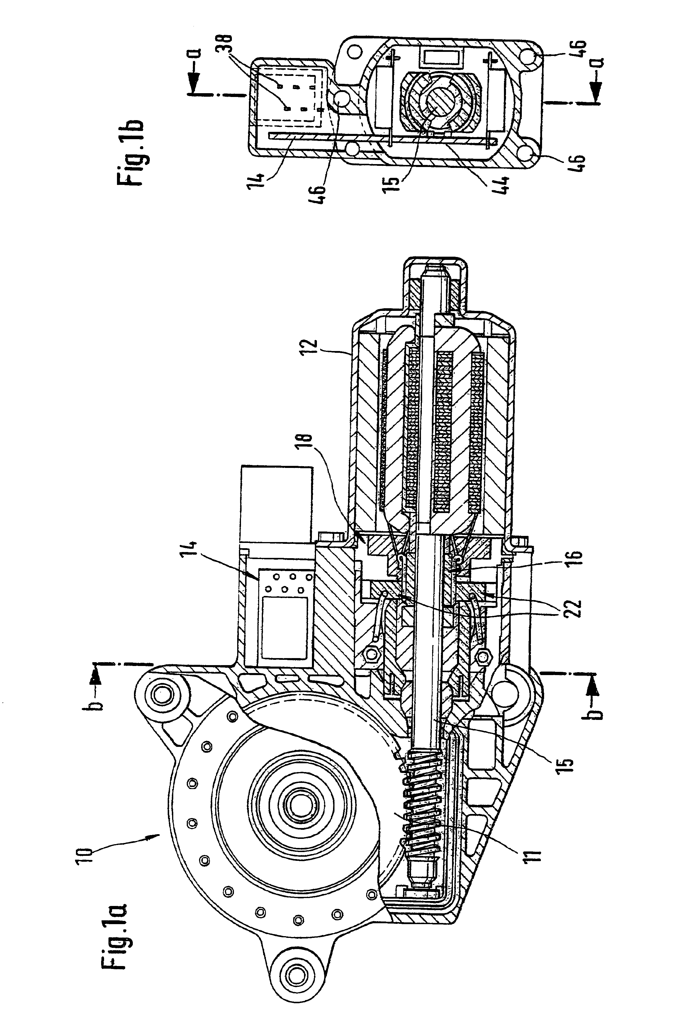
FIGS. 1a and 1b show an electric motor whereby an essentially rectangular printed circuit board 14 is arranged between a transmission housing 10 with a transmission 11 and a pole housing 12. To accomplish this the pole housing 12 was shortened so that a commutator 16 located on a armature shaft 15 extends out over the pole housing 12. A brush holder 18 which is held by the pole housing 12 and the transmission housing 10 carries brushes 22 which are engaged with the commutator 16.

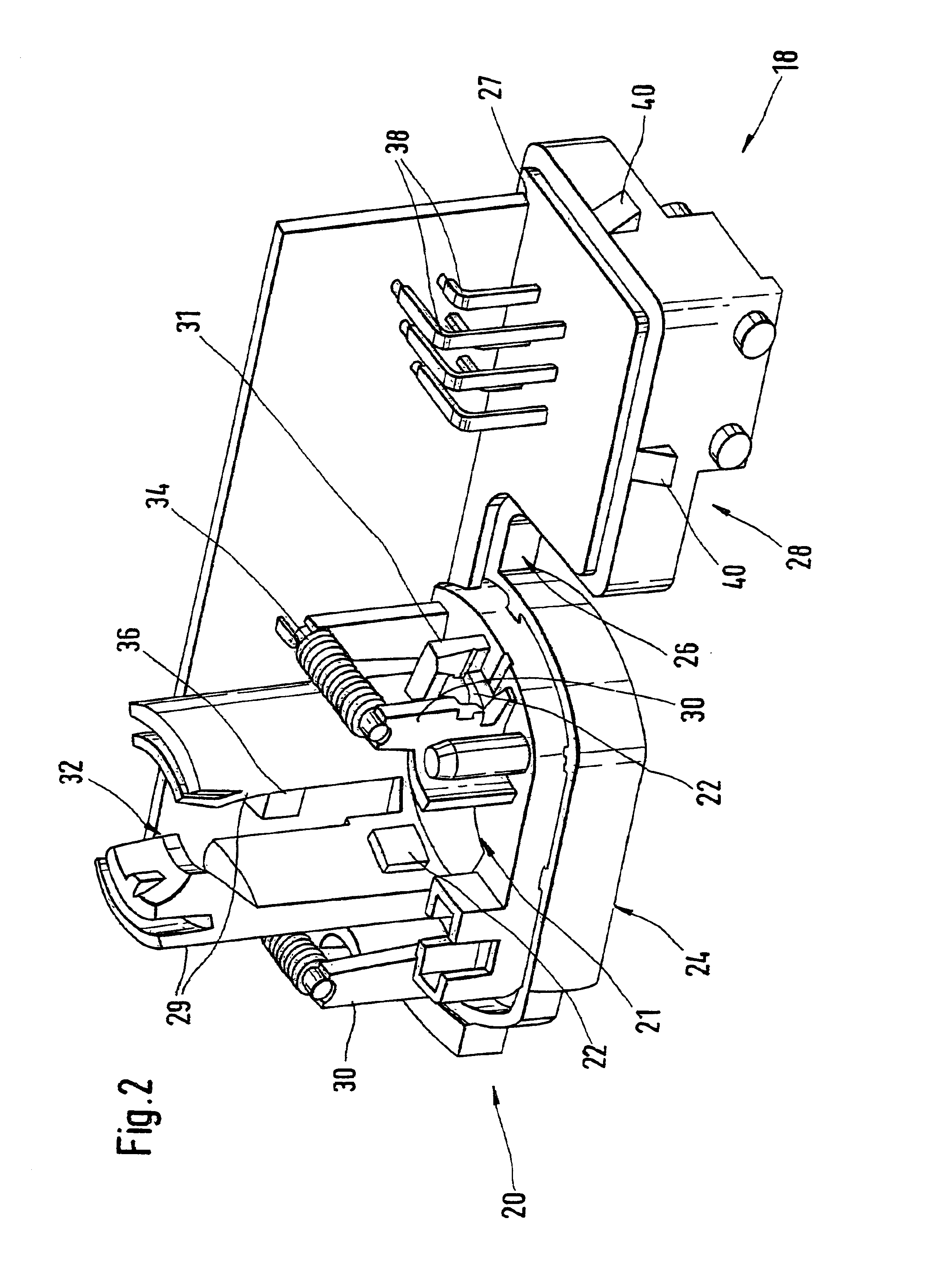
FIG. 2 shows the brush holder 18 with the printed circuit board 14 in detail. The brush holder 18 has essentially three areas: one is an essentially round plastic ring 20 flattened on two opposite sides and held by the pole housing 12 and the transmission housing 10; one is a web 26 parallel to the flattened sides; and one is a connector plug 26 which is supported by the web 26. The inner recess of the plastic ring 20 is identified in the following with reference number 21. The brush holder includes a recept...


PUM


Abstract

Electric motor, in particular for raising and lowering panes in a motor vehicle having a transmission (11) and a transmission housing (10) and control electronics located in the transmission housing (10) such that the control electronics has precisely one essentially rectangular printed circuit board located in the transmission housing (10).

Description

PRIOR ARTThe invention pertains to an electric motor, in particular for raising and lowering panes in a motor vehicle according to the type of the independent claims. Numerous electric motors for this purpose are already known, for example from EP 0 474 904 B1. The electric motor shown in this patent document shows a transmission and integrated control electronics with a printed circuit board on which the commutator of the electric motor are located. Since the distance between the pole housing and the transmission housing in which the commutator of the electric motor is arranged is very short, the printed circuit board has an extension which guides the brushes of the electric motor to the commutator located on the armature shaft. This form is both cumbersome and expensive both from a manufacturing and an assembly perspective, in particular when Hall sensors need to be located in the area of the armature shaft for monitoring a transmission position.ADVANTAGES OF THE INVENTIONThe elec...

Claims


Application Information

Patent Timeline
Patent Type & Authority Patents(United States)
IPC IPC(8): H02K7/116H02K5/14H02K5/22H02K23/66H02K7/08H02K5/167H02K11/02H02K11/04B60J1/17H02K11/026H02K13/00
CPCH02K5/148H02K5/225H02K7/1166H02K23/66H02K5/1672H02K7/081H02K11/026H02K11/044H02K2211/03H02K11/05H02K7/116
Inventor HAGER, MARTINHUCK, THOMAS
Owner ROBERT BOSCH GMBH
Learn More