Railroad collision avoidance system and method for preventing train accidents

a collision avoidance system and train technology, applied in the rail field, can solve the problems of inacceptable number of train-vehicle accidents, interference from other radios, and 200,000 railroad crossings are passive railroad crossings,

Inactive Publication Date: 2004-07-06
TIME DOMAIN
View PDF24 Cites 132 Cited by
  • Summary
  • Abstract
  • Description
  • Claims
  • Application Information

AI Technical Summary

Problems solved by technology

This means that over 200,000 railroad crossings are passive railroad crossings which are particularly dangerous since they have no warning lights or retractable gates to warn a motorist that a locomotive is approaching the railroad crossing.
Even with the use of conventional railroad collision avoidance systems at the active railroad crossings and the lack of collision avoidance systems at passive railroad crossings there is still an unacceptable number of train-vehicle accidents.
Unfortunately, the wireless railroad grade crossing motorist warning system uses conventional radio communication technology and as such suffers from the traditional problems associated with that technology including, for example, interference from other radios, high power consumption and multipath interference.
While this system is an improvement over many others it is still subject to interference from other transmitters and must operate within an assigned frequency that can be adversely affected by different types of interference commonly associated with traditional communication technology.
Such codes are commonly referred to as time-hopping codes or pseudo-noise (PN) codes since their use typically causes inter-pulse spacing to have a seemingly random nature.
band. It can also be observed from FIG. 2A that impulse transmission systems typically have very low average duty cycles, resulting in average power lower than peak
As the number of coincidences increases, the propensity for data errors increases.
Generally, keeping the number of pulse collisions minimal represents a substantial attenuation of the unwanted signal.
Such `random-like` codes are attractive for certain applications since they tend to spread spectral energy over multiple frequencies while having `good enough` correlation properties, whereas designed codes may have superior correlation properties but possess less suitable spectral properties.
Impulse radio systems operating within close proximity to each other may cause mutual interference.
While coding minimizes mutual interference, the probability of pulse collisions increases as the number of coexisting impulse radio systems rises.
Additionally, various other signals may be present that cause interference.
However, when the transmitted impulse signal is coded and the impulse radio receiver template signal 506 is synchronized using the identical code, the receiver samples the interfering signals non-uniformly.
Multipath fading effects are most adverse where a direct path signal is weak relative to multipath signals, which represents the majority of the potential coverage area of a radio system.
This characteristic has been the subject of much research and can be partially improved by such techniques as antenna and frequency diversity, but these techniques result in additional complexity and cost.
Narrow band systems, on the other hand, are limited to the modulation envelope and cannot easily distinguish precisely which RF cycle is associated with each data bit because the cycle-to-cycle amplitude differences are so small they are masked by link or system noise.

Method used


Image

  • Railroad collision avoidance system and method for preventing train accidents
  • Railroad collision avoidance system and method for preventing train accidents
  • Railroad collision avoidance system and method for preventing train accidents

Examples


first embodiment

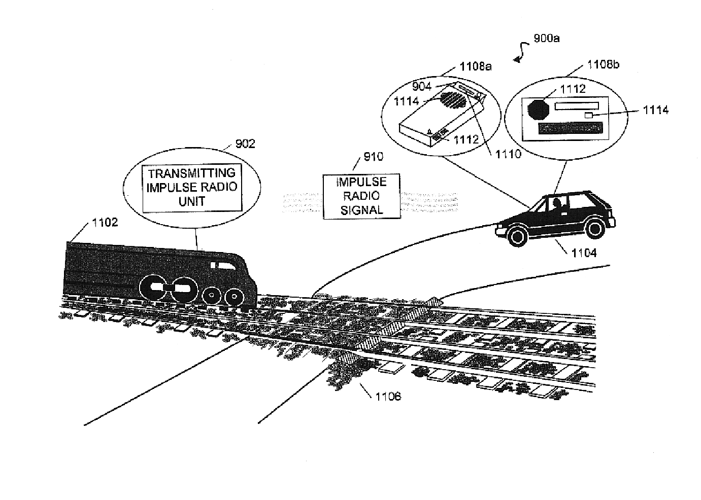
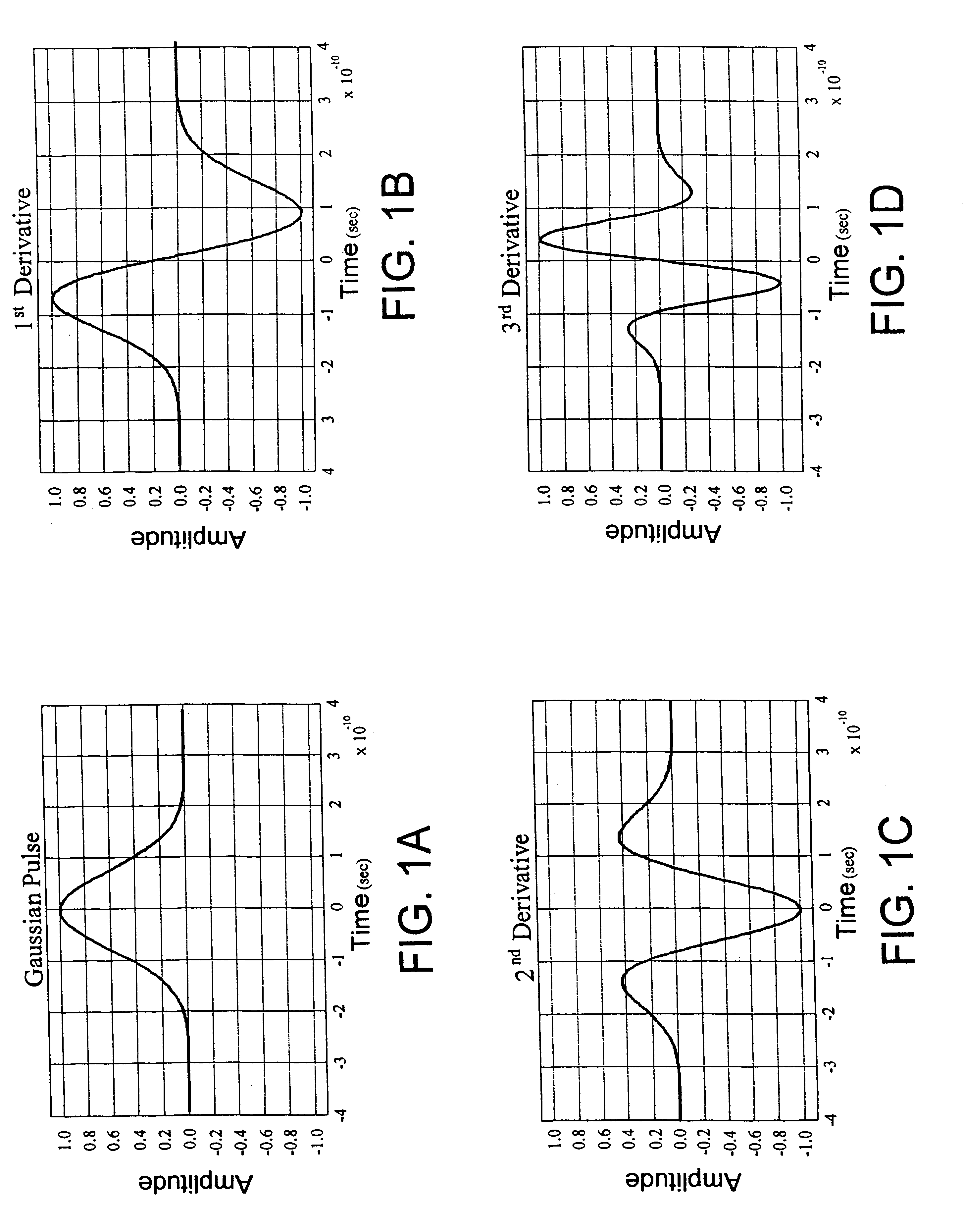
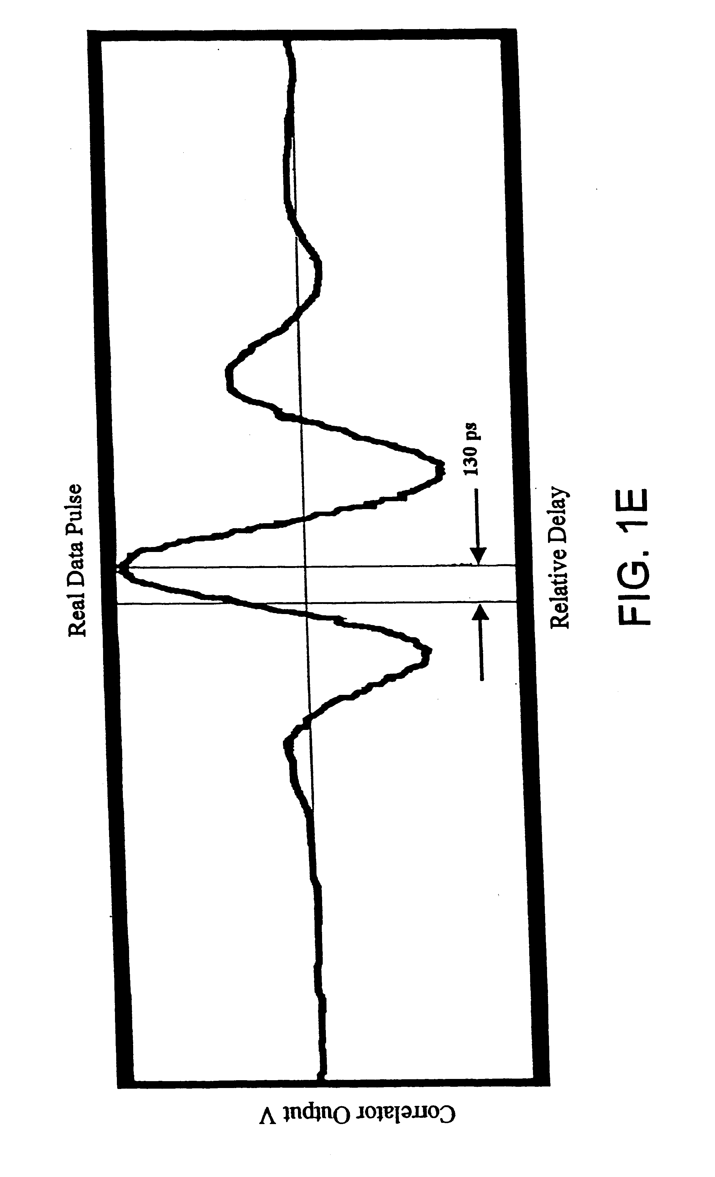
Referring to FIGS. 11 and 12, there are diagrams illustrating in greater detail the components and steps of the railroad collision avoidance system 900a and method 1000a. In this embodiment, the railroad collision avoidance system 900 includes a transmitting impulse radio unit 902 coupled (step 1202) to a locomotive 1102 and a receiving impulse radio unit 904 coupled (step 1204) to a vehicle 1104 (shown as a car). The transmitting impulse radio unit 902 operates to transmit (step 1206) an impulse radio signal 910 having a known pseudorandom sequence of pulses that look like a series of Gaussian waveforms (see FIGS. 1-3) towards the receiving impulse radio unit 904 attached to the vehicle 1104. In particular, the transmitting impulse radio unit 902 may continually transmit the impulse radio signal 910 or it may transmit the impulse radio signal 910 whenever a whistle (for example) on the locomotive 1102 is activated to indicate that the locomotive 1102 is a predetermined distance fro...

second embodiment

Referring to FIGS. 13 and 14, there are diagrams illustrating in greater detail the components and steps of the railroad collision avoidance system 900b and method 1000b. In this embodiment, the railroad collision avoidance system 900b includes a transmitting impulse radio unit 902 coupled (step 1402) to a locomotive 1102 and a receiving impulse radio unit 904 coupled (step 1404) to an active railroad pole 1302. The transmitting impulse radio unit 902 operates to transmit (step 1406) an impulse radio signal 910 having a known pseudorandom sequence of pulses that look like a series of Gaussian waveforms (see FIGS. 1-3) towards the receiving impulse radio unit 904 attached to the railroad pole 1302 (two are shown). In particular, the transmitting impulse radio unit 902 may continually transmit the impulse radio signal 910 or it may transmit the impulse radio signal 910 whenever a whistle (for example) on the locomotive 1302 is activated to indicate that the locomotive 1302 is about to...

third embodiment

Referring to FIGS. 15 and 16, there are diagrams illustrating in greater detail the components and steps of the railroad collision avoidance system 900c and method 1000c. In this embodiment, the railroad collision avoidance system 900c includes a transmitting impulse radio unit 902 coupled (step 1602) to a control box 1502 and a receiving impulse radio unit 904 coupled (step 1604) to a vehicle 1104. The control box 1502 is located next to railroad tracks 1504 and is capable of using a sensor 1506 (e.g., electromagnetic sensor, motion detector, percussion sensor) to sense the presence of a locomotive 1102. Moreover, the control box 1502 can be powered by a variety of power sources including, for example, a solar battery or a power line.

The transmitting impulse radio unit 902 operates to transmit an impulse radio signal 910 having a known pseudorandom sequence of pulses that look like a series of Gaussian waveforms (see FIGS. 1-3) towards the receiving impulse radio unit 904 attached ...


PUM


Abstract

A railroad collision avoidance system and method are disclosed that utilize impulse radio technology to effectively warn a person when there is a locomotive in their vicinity. In one embodiment, the railroad collision avoidance system includes a transmitting impulse radio unit coupled to a locomotive and a receiving impulse radio unit coupled to a vehicle. The transmitting impulse radio unit operates to transmit an impulse radio signal towards the vehicle when the locomotive is a predetermined distance from a railroad crossing. Upon receiving the impulse radio signal, the receiving impulse radio unit makes sure the person operating the vehicle is informed about the potentially dangerous situation. Several embodiments of the railroad collision avoidance system and method are disclosed all of which operate to warn a person when there is a locomotive in their vicinity.

Description

1. Field of the InventionThe present invention generally relates to the railroad field and, in particular, to a railroad collision avoidance system and method for preventing train accidents.2. Description of Related ArtWhen it comes to public safety and personal safety, it is always desirable to improve upon the way people are warned about potentially dangerous situations involving a locomotive. To date there does not appear to be any railroad collision avoidance system that can effectively warn a person when there is a locomotive in their vicinity. Presently, there are approximately 259,000 railroad crossings in the United States of which approximately 22% are active railroad crossings which means that they are protected by some sort of railroad collision avoidance system. The conventional railroad collision avoidance system uses warning lights and retractable gates to alert a motorist that there is an oncoming locomotive. This means that over 200,000 railroad crossings are passive...

Claims


Application Information

Patent Timeline
Patent Type & Authority Patents(United States)
IPC IPC(8): B61L29/00B61L29/24
CPCB61L29/246
Inventor GRISHAM, WILLIAM T.ROBERTS, MARK D.
Owner TIME DOMAIN
Why Eureka
Try Eureka