Apparatus for simulating ride on vehicle

a technology for vehicles and apparatus, applied in the field of apparatus for simulating rides on vehicles, can solve the problems of increasing the number of parts and increasing the cos

Inactive Publication Date: 2004-07-20
HONDA MOTOR CO LTD
View PDF11 Cites 82 Cited by
  • Summary
  • Abstract
  • Description
  • Claims
  • Application Information

AI Technical Summary

Problems solved by technology

Therefore, the number of parts increases and the cost becomes higher.

Method used


Image

  • Apparatus for simulating ride on vehicle
  • Apparatus for simulating ride on vehicle
  • Apparatus for simulating ride on vehicle

Examples


Embodiment Construction

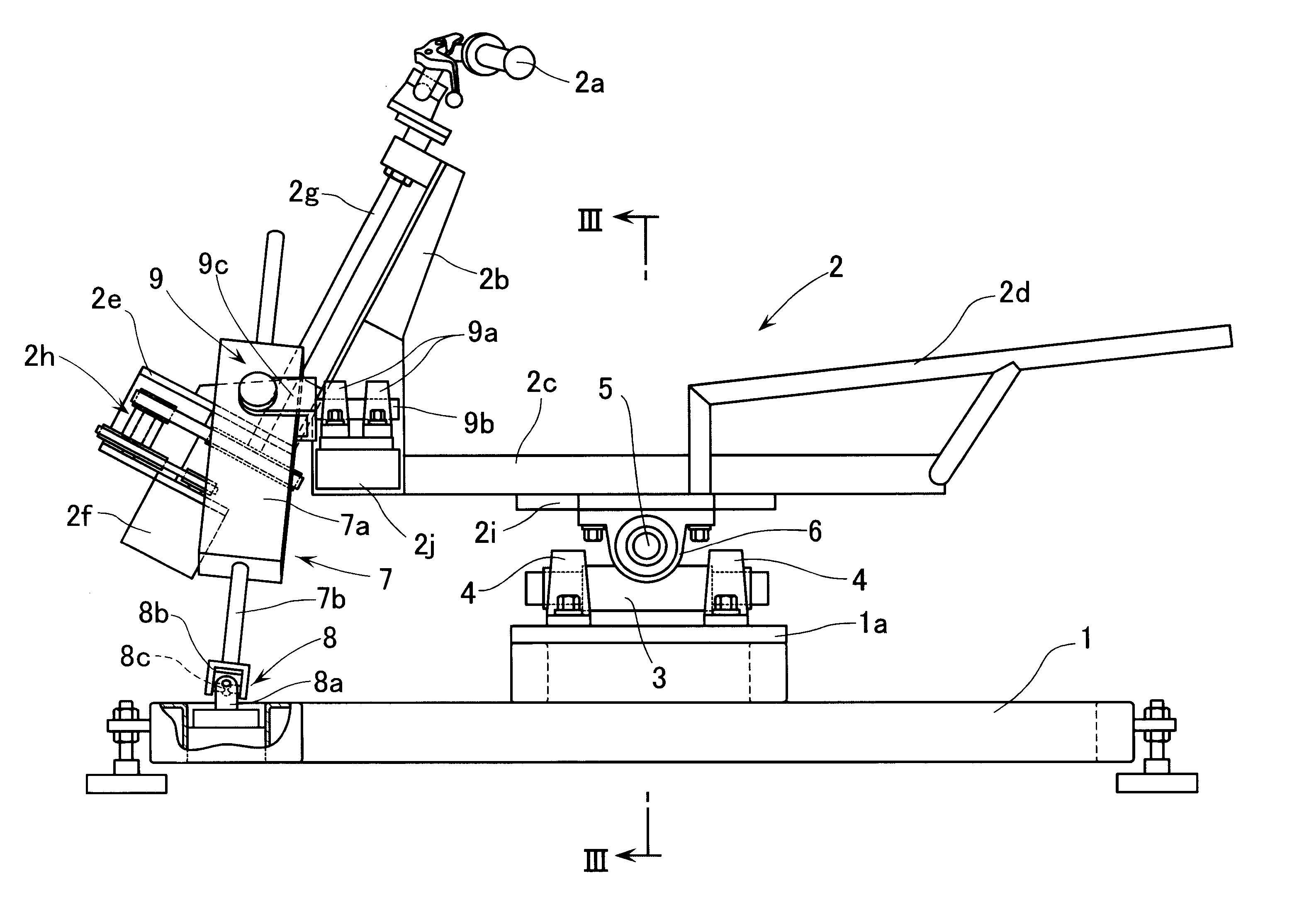
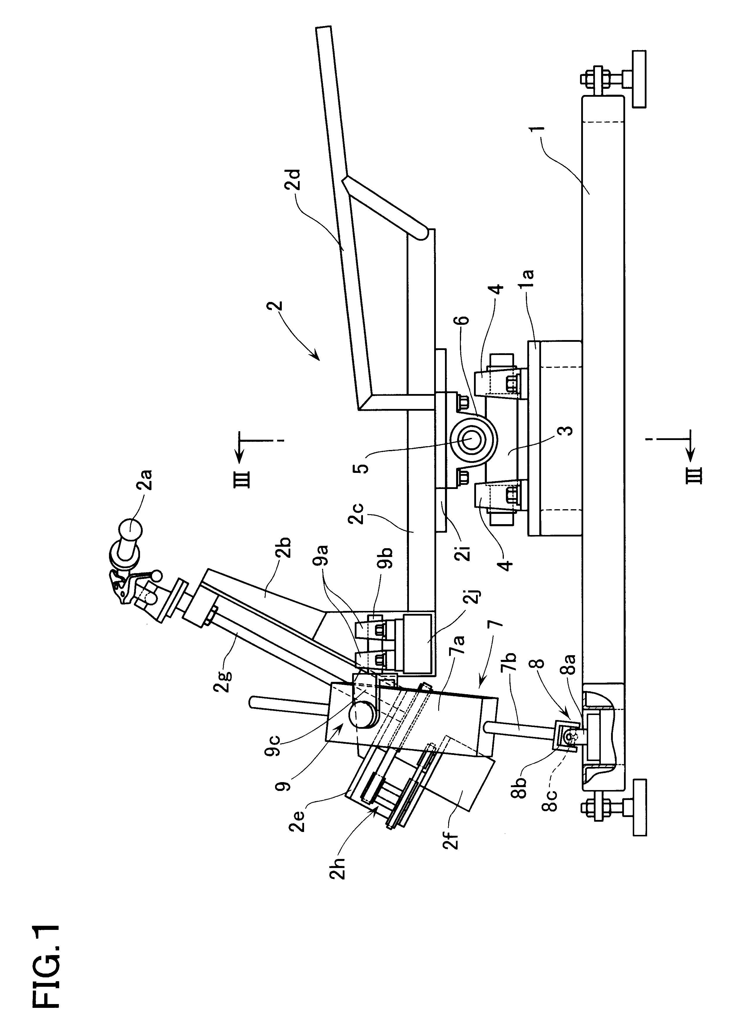
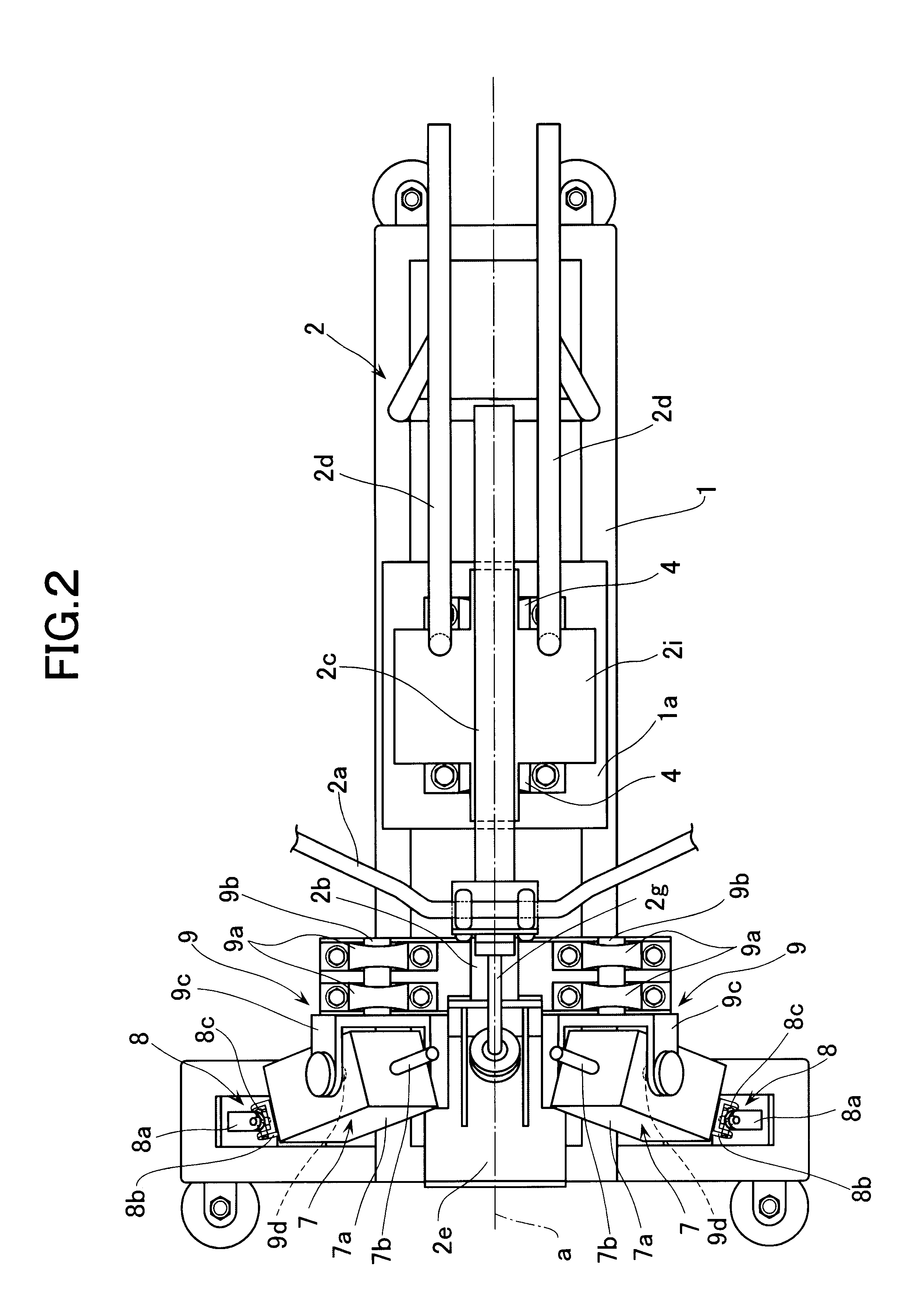
FIGS. 1 and 2 represent an apparatus for simulating a ride on a motorcycle. This apparatus is provided with a base 1 and a simulated vehicle body 2 which is supported on the base 1 with a freedom of two-axis rotation which is described in more detail hereinbelow.

The simulated vehicle body 2 is provided with: a front column 2b having at an upper end thereof a handle 2a for steering the simulated vehicle body 2; a main frame 2c which is elongated backwards from a lower end of the front column 2b; and a rear frame 2d which is provided on a rear upper portion of the main frame 2c. It is thus so arranged that a rider or an operator of the apparatus can sit or ride on a seat (not illustrated) which is to be mounted on the rear frame 2d. The front column 2b is further provided at a lower end thereof with a supporting frame 2e which protrudes forward. An electric motor 2f is mounted on the supporting frame 2e. The electric motor 2f is coupled through a reduction (speed reducing) mechanism 2...


PUM


Abstract

An apparatus for simulating a ride on a vehicle has a base, and a simulated vehicle body which is supported on the base with a freedom of two-axis rotation about a rolling axis and a pitching axis. A pair of linear actuators are disposed in a position offset to one side in an axial direction of one of the rolling axis and the pitching axis, e.g., offset to one axial side of the rolling axis relative to the pitching axis. The actuators are disposed symmetrically relative to a plane which crosses the pitching axis at a right angle and which includes an axial line of the rolling axis. A fixing member and a movable member of each of the actuators are coupled to the base and the simulated vehicle body, respectively, through universal joints.

Description

1. Field of the InventionThe present invention relates to an apparatus for simulating a ride on a vehicle, the apparatus having a simulated vehicle body on which a rider or an operator can ride.2. Description of Related ArtAs this kind of apparatus for simulating a ride on a vehicle, there has hitherto been known the following in Published Unexamined Japanese Patent Application No. 30950 / 1999. Namely, a simulated vehicle body is supported on a base with a freedom of two-axis rotation so as to be rotatable about a first axis and a second axis which crosses the first axis at a right angle. By means of a pair of linear actuators (linearly-acting actuators), a rotation about the first axis and a rotation about the second axis are given to the simulated vehicle body. In this apparatus, each of the linear actuators is disposed in a posture approximately parallel to one of the first axis and the second axis. A fixing member of each of the linear actuators is coupled to the base through a s...

Claims


Application Information

Patent Timeline
Patent Type & Authority Patents(United States)
IPC IPC(8): G09B9/04G09B9/058
CPCG09B9/058
Inventor ICHIHASHI, SATORUKAI, MASAYOSHIOKAMURA, RYUICHINEGISHI, KUNIKAZUMASAKI, TAKESHI
Owner HONDA MOTOR CO LTD
Why Eureka
Try Eureka