System to automatically detect eye corneal striae

a technology of eye corneal striae and automatic detection, which is applied in the field of ophthalmic refractive correction procedures and ophthalmic instruments, can solve the problems of postoperative refractive problems of patients, corneal flap striae, and wrinkles in the corneal flap

Inactive Publication Date: 2004-07-20
MEMPHIS EYE & CATARACT ASSOCS AMBULATORY SURGERY CENT
View PDF26 Cites 30 Cited by
  • Summary
  • Abstract
  • Description
  • Claims
  • Application Information

AI Technical Summary

Benefits of technology

It is another object of the invention to provide an automated technique for detecting eye corneal striae after LASIK refractive surgery which is faster than existing manual techniques.
It is a further object of the invention to provide an automated technique for detecting eye corneal striae after LASIK refractive surgery which will aid in the reduction of patient revisits to correct eye corneal striae problems.

Problems solved by technology

Although this procedure does possess many advantages over PRK, it has one drawback that can cause postoperative refractive problems for the patient.
This drawback is termed corneal flap striae, which is basically a wrinkle in the corneal flap, created when the flap is not uniformly reattached to the cornea.
This striae, or wrinkle, can cause vision problems in the patient ranging from glare to acuity problems due to irregular astigmatism.
However, even this approach does not guarantee that there will be no striae present nor does it automate the detection of striae.
This detector is part of an expensive interferometer system used to measure the striae present in the glass.
This approach would not work for eye corneal striae detection as one cannot place a detector on the other side of the cornea.
Additionally, the interferometer requires precise alignment and would be too expensive for this application.
Thus, there is no present method for automatically detecting eye corneal striae following LASIK refractive surgery.

Method used


Image

  • System to automatically detect eye corneal striae
  • System to automatically detect eye corneal striae
  • System to automatically detect eye corneal striae

Examples


Embodiment Construction

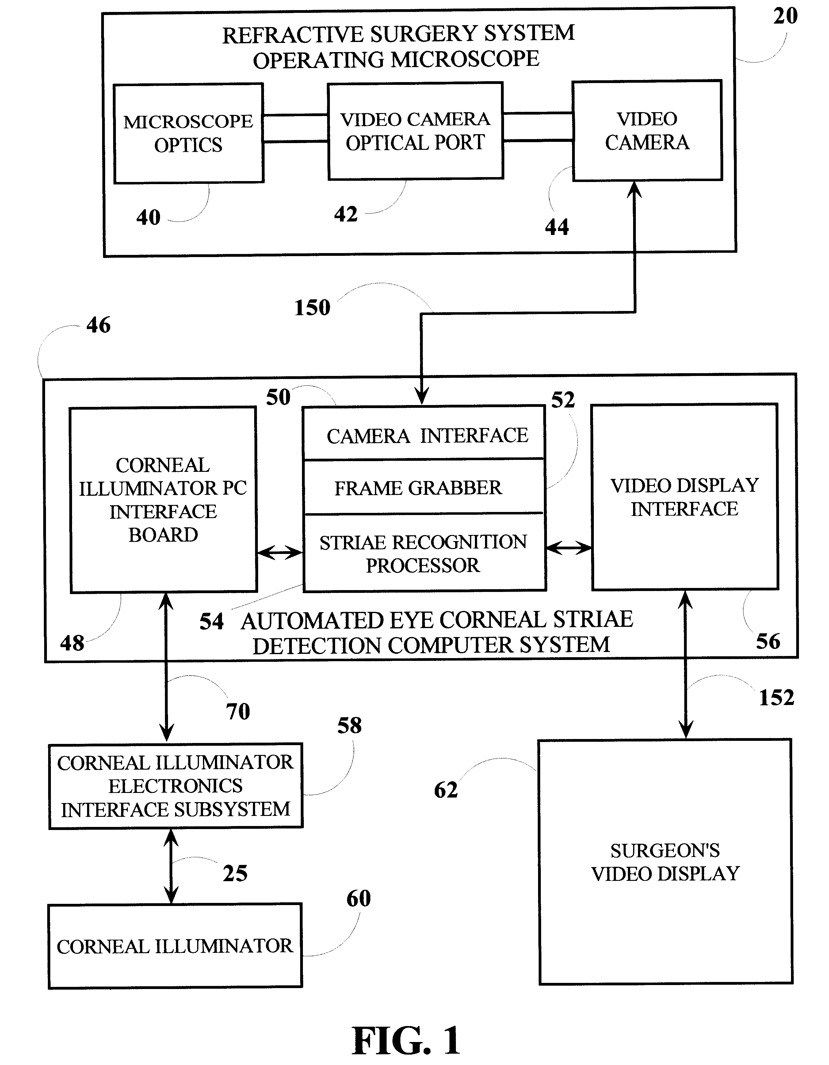
Turning now to FIG. 1, a refractive surgery system operating microscope 20 is coupled to an automated eye corneal striae detection computer system 46 of the invention. Refractive surgery system operating microscope 20 includes a set of microscope optics 40 to allow the surgeon adequate view of the corneal surface and a video camera optical port 42 that optically couples the image the surgeon views to a video camera 44, e.g., a Sony XC-75, that is used to capture the corneal image seen in FIG. 5. An automated eye corneal striae detection computer system 46, e.g., a Compaq Deskpro EN, 450-MHz PC, generally includes a video camera interface 50 which is coupled to the video-out port of video camera 44 through a video camera cable 150, a frame grabber 52, e.g., a National Instruments PCI 1408, a video display interface 56 which is coupled to a surgeon's video display 62 through a video display cable 152, a corneal illuminator PC interface board 48, e.g., a National Instruments PCI-6503, ...


PUM


Abstract

An automated eye corneal striae detection system for use with a refractive laser system includes a cornea illuminator, a video camera interface, a computer, and a video display for showing possible eye corneal striae to the surgeon. The computer includes an interface to control the corneal illuminator, a video frame grabber which extracts images of the eye cornea from the video camera, and is programmed to detect and recognize eye corneal striae. The striae detection algorithm finds possible cornea striae, determines their location, or position, on the cornea and analyzes their shape. After all possible eye corneal striae are detected and analyzed, they are displayed for the surgeon on an external video display. The surgeon can then make a determination as to whether the corneal LASIK flap should be refloated, adjusted or smoothed again.

Description

Not applicable.1. Field of InventionThe present invention relates to ophthalmic surgical procedures for the correction of refractive error. More particularly, the present invention relates to an ophthalmic refractive correction procedure known as LASIK, wherein a corneal flap is produced. Still more particularly, the present invention relates to an ophthalmic instrument and method which automates the detection of eye corneal striae, or corneal wrinkles, following the LASIK procedure.2. Description of Prior ArtLaser refractive surgery has become a very popular method for providing patients with better vision. The majority of laser refractive surgery patients will have the procedure termed LASIK (Laser In-Situ Keratomileusis) performed. There are some very important advantages that have caused LASIK to be used over the original Photo-Refractive Keratectomy (PRK) technique. For example, the healing process is usually shorter and more comfortable for the patient and larger refractive co...

Claims


Application Information

Patent Timeline
Patent Type & Authority Patents(United States)
IPC IPC(8): A61B3/13G06T7/00
CPCA61B3/13G06T7/0012
Inventor FREEMAN, JAMES F.WILLIAMS, ROY E.
Owner MEMPHIS EYE & CATARACT ASSOCS AMBULATORY SURGERY CENT
Why Eureka
Try Eureka