
Hemodiafiltration system and method

a technology of hemodiafiltration system and filter, which is applied in the direction of gravity filter, feed/discharge tank, medical devices, etc., can solve the problems of complex operation of the hemodiafiltration apparatus with blood filter connected in series, and cannot be used in commercially available dialysis machines, special regenerators, purifying the ultrafiltrate,

Inactive Publication Date: 2004-08-17
MEMBRANA
View PDF17 Cites 81 Cited by
  • Summary
  • Abstract
  • Description
  • Claims
  • Application Information

AI Technical Summary

Problems solved by technology

However, with an endotoxin concentration of <0.03 EU / ml, which is the detection limit of the conventional LAL tests, CIS might still be present in the dialyzate.
Such hemodiafiltration apparatus with blood filters connected in series are complex in operation and can generally not be used in commercially available dialysis machines due to the design and the special and complex controls associated with it.
In addition to the previously cited disadvantages of separate blood filters connected in series, the hemodiafiltration apparatus described in EP-A 451 429 has the drawback that it requires a special regenerator that must be used to purify the ultrafiltrate.
While the hemodiafiltration system described in DE-A 196 07 162 has a simpler and clearer construction compared to the systems with multiple blood filters connected in series, the manufacture of the two-module dialyzers disclosed in DE-A 196 07 162 is difficult, particularly due in part to the handling of two different hollow-fiber membrane bundles.
Furthermore, the membrane modules in the dialyzer are not arranged rotationally symmetrically, so that there is a risk of non-uniform flow, in particular through the external space surrounding the hollow-fiber membranes of the first membrane module, which is used for hemodiafiltration.

Method used


Image

  • Hemodiafiltration system and method
  • Hemodiafiltration system and method
  • Hemodiafiltration system and method

Examples


Embodiment Construction

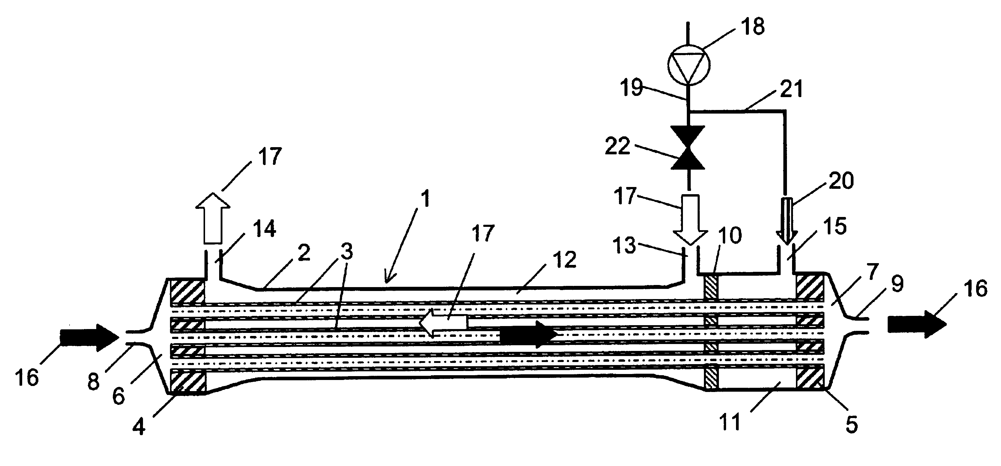
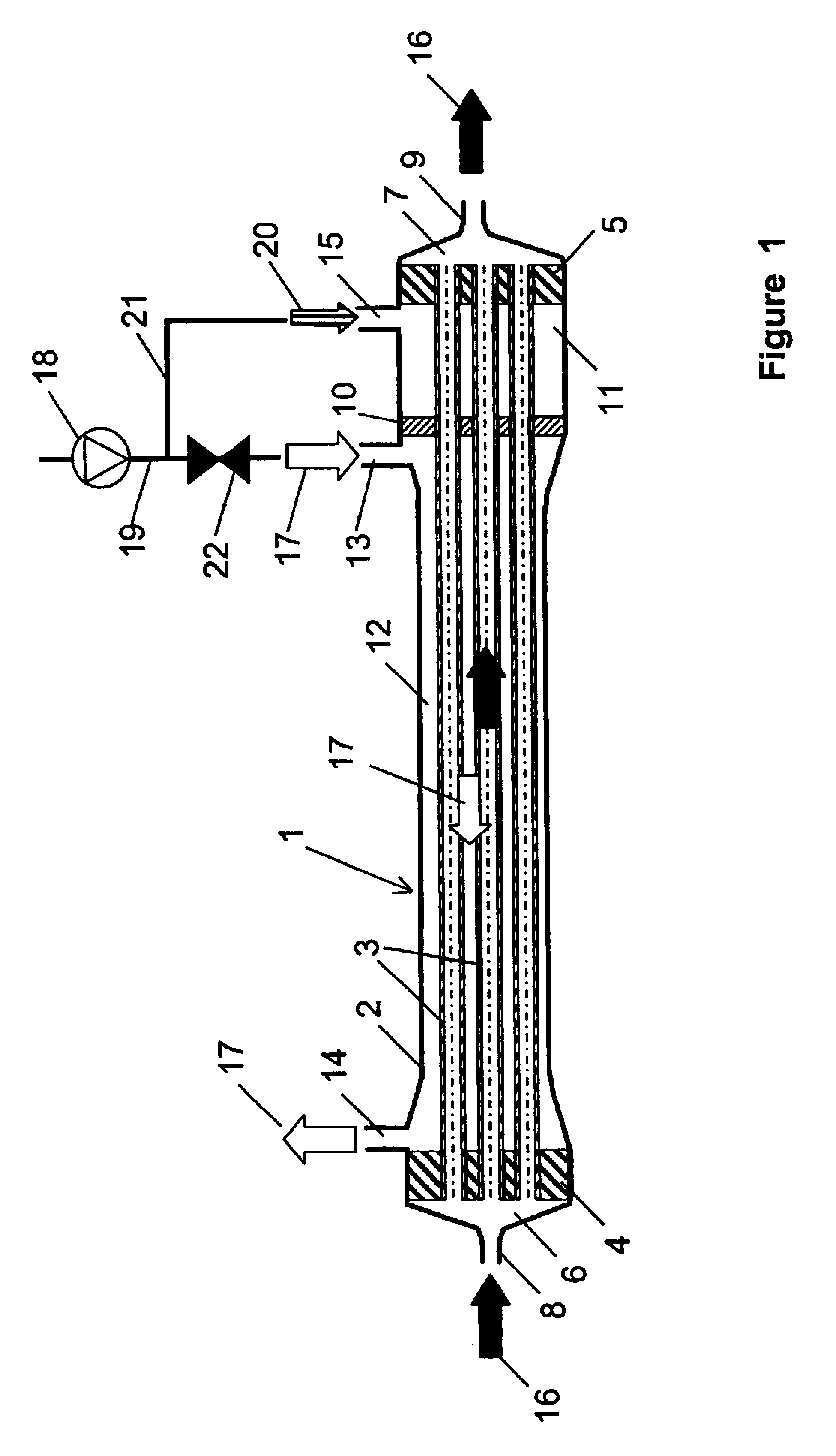
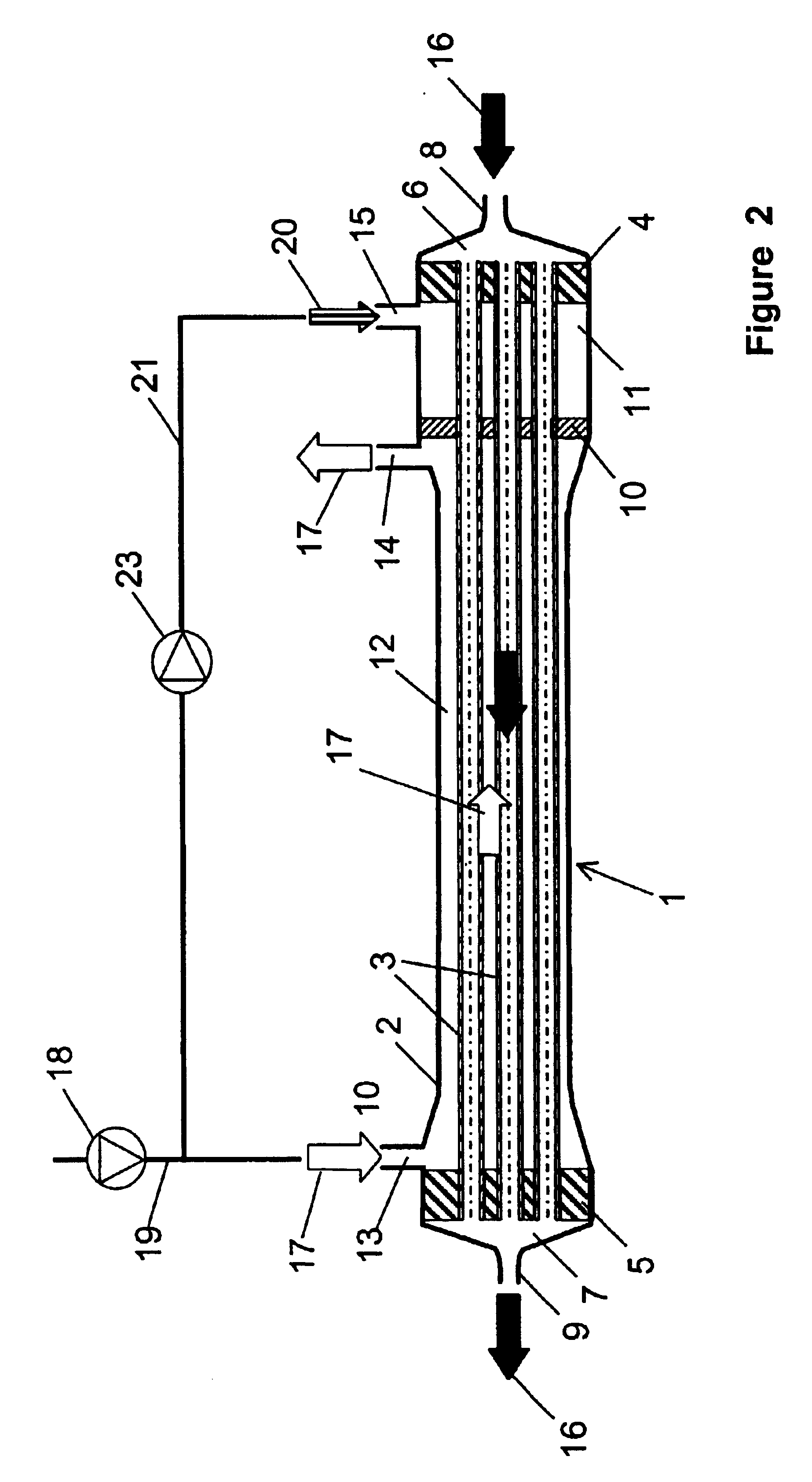
In the membrane module of the hemodiafiltration system of the invention, the ends of the hollow-fiber membranes are each embedded in a fluid-tight manner in sealing compounds that also seal off the exterior space formed around the hollow fibers with respect to a distribution space, in which the blood to be treated and introduced into the distribution space via a blood inlet arrangement is distributed to the lumina of the hollow-fiber membranes, and with respect to a collection space in which the blood flowing from the lumina is collected and withdrawn from the module via a blood outlet arrangement. The ends, open on the face, of the hollow-fiber membranes extend through the respective sealing compound and are in communication with the distribution and collection spaces via the lumina, so that the blood to be treated can pass through the membranes.

Due to the fact that in the membrane module used in the hemodiafiltration system of the invention, the same hollow-fiber membranes are use...


PUM

PropertyMeasurementUnit
Volumeaaaaaaaaaa
Volumeaaaaaaaaaa
Thicknessaaaaaaaaaa

Abstract

A hemodiafiltration system for treating blood which has module having a housing in which hollow-fiber membranes are arranged in the direction of the longitudinal extent and are embedded at their ends in first and second sealing compounds joined to the inner wall of the housing in a fluid-tight manner. The membrane module also has a dialyzate space and a substituate space separated from the dialyzate space in a fluid-tight manner by a continuous dividing wall. The membrane module further includes means for delivering and withdrawing a dialyzate to and from the dialyzate space, and means for delivering a substituate to the substituate space. The hollow-fiber membranes are used for blood treatment, filtration of the substituate, and delivery of the substituate to the blood. An exterior space is formed around the hollow-fiber membranes that is delimited by the inner wall of the housing and sealing compounds and is divided along the longitudinal extent of the housing by a dividing wall into the substituate space and the dialyzate space, the dividing wall encloses each individual hollow-fiber membrane.

Description

1. Field of the InventionThe invention relates to a hemodiafiltration system for treating blood, comprising a membrane module having a cylinder-shaped housing with a longitudinal extent, in which housing is included a bundle of hollow-fiber membranes having semipermeable walls capable of supporting fluid flow through their lumina. The ends of the hollow-fiber membranes are embedded in a manner in first and second sealing compounds joined to the housing inner wall in a fluid-tight manner and are arranged in the direction of the longitudinal extent. There is a dialyzate space into which a dialyzate inlet arrangement and a dialyzate outlet arrangement open, as well as a substituate space into which a substituate inlet arrangement opens, a means for delivering a dialyzate with a defined volume stream into the dialyzate space via the dialyzate inlet arrangement, a means for withdrawing the dialyzate from the dialyzate space via the dialyzate outlet arrangement, and a means for delivering...

Claims


Application Information

Patent Timeline
IPC IPC(8): A61M1/34B01D63/02B01D61/58A61M1/16A61M1/14A61M1/18B01D61/14B01D61/28B01D61/32B01D63/06B01D63/08
CPCA61M1/3413B01D61/58B01D63/02A61M1/1635A61M1/1672A61M1/3431A61M1/3437A61M1/3465B01D61/145B01D61/243B01D2313/04B01D2313/19B01D2313/23B01D2313/90A61M1/3441B01D2313/903
Inventor BAURMEISTER, ULRICH
Owner MEMBRANA
Learn More