Abnormality detector for a motor drive system
a motor drive system and detector technology, applied in the direction of electrical control, electrical control, electric programme control, etc., can solve the problems of difficult maintenance work, difficult extraction and detection of abnormal phases, and failure to detect abnormalities for each phas
- Summary
- Abstract
- Description
- Claims
- Application Information
AI Technical Summary
Benefits of technology
Problems solved by technology
Method used
Image
Examples
embodiment 1
2. Detailed Description of Operation in Embodiment 1
first embodiment
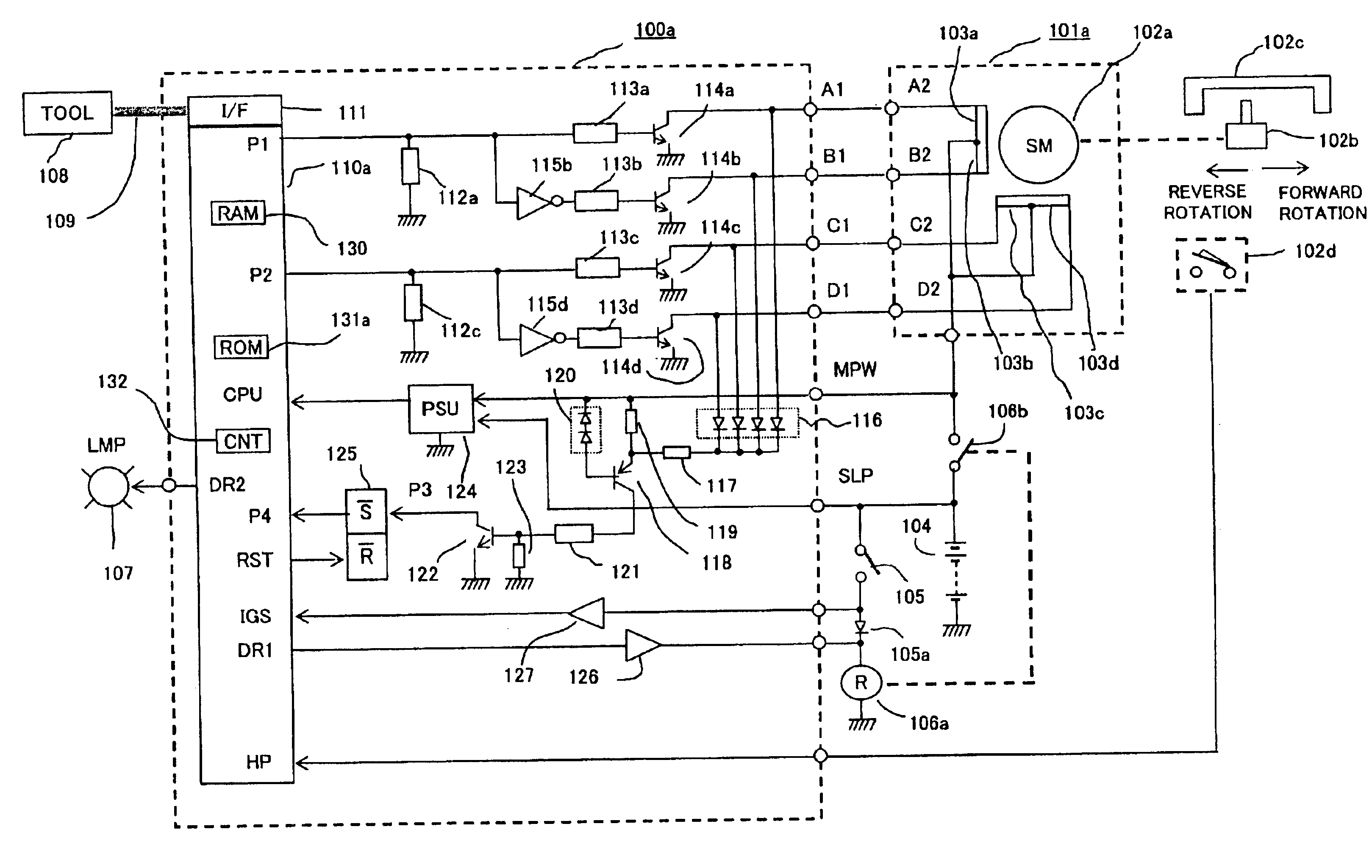
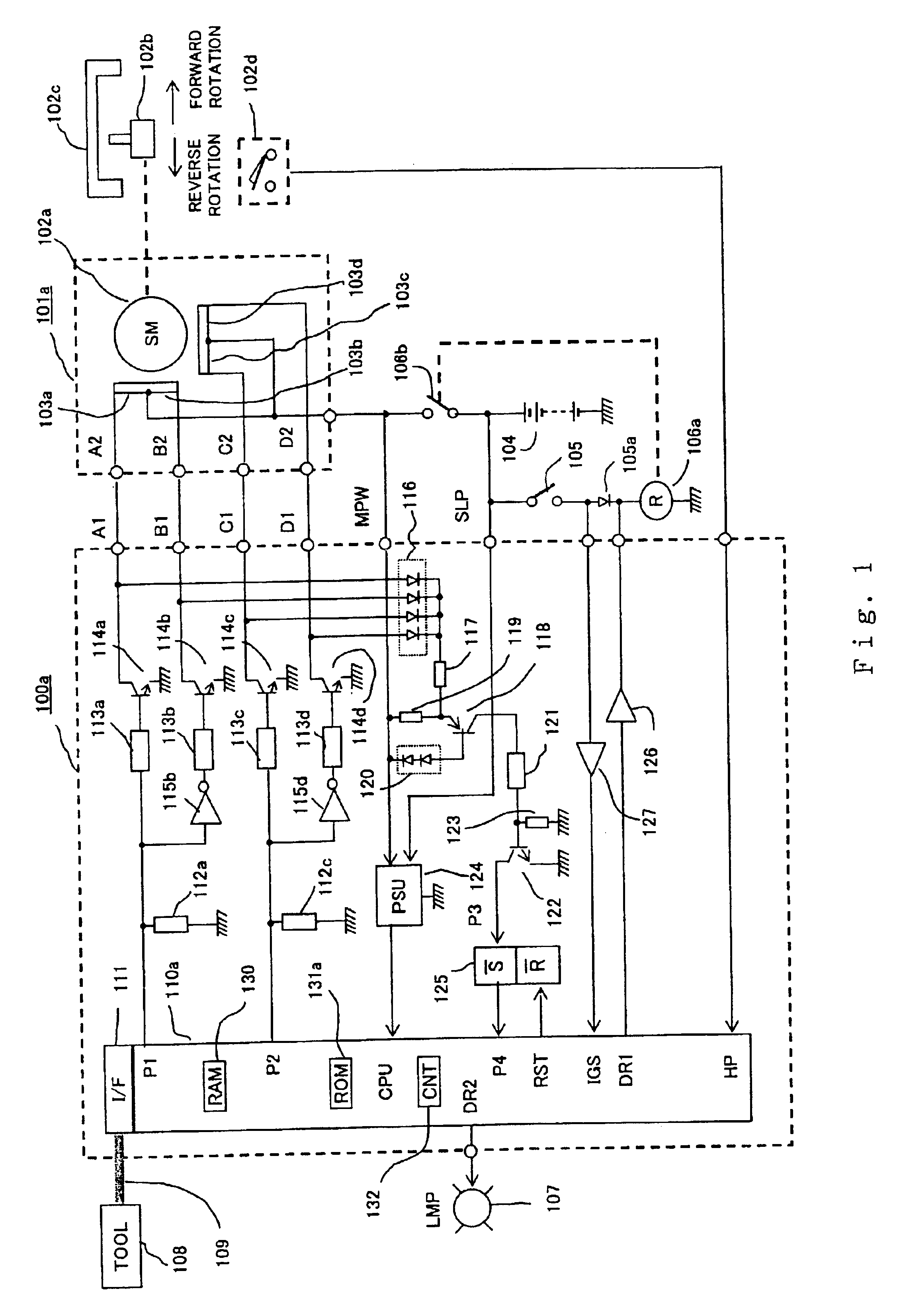
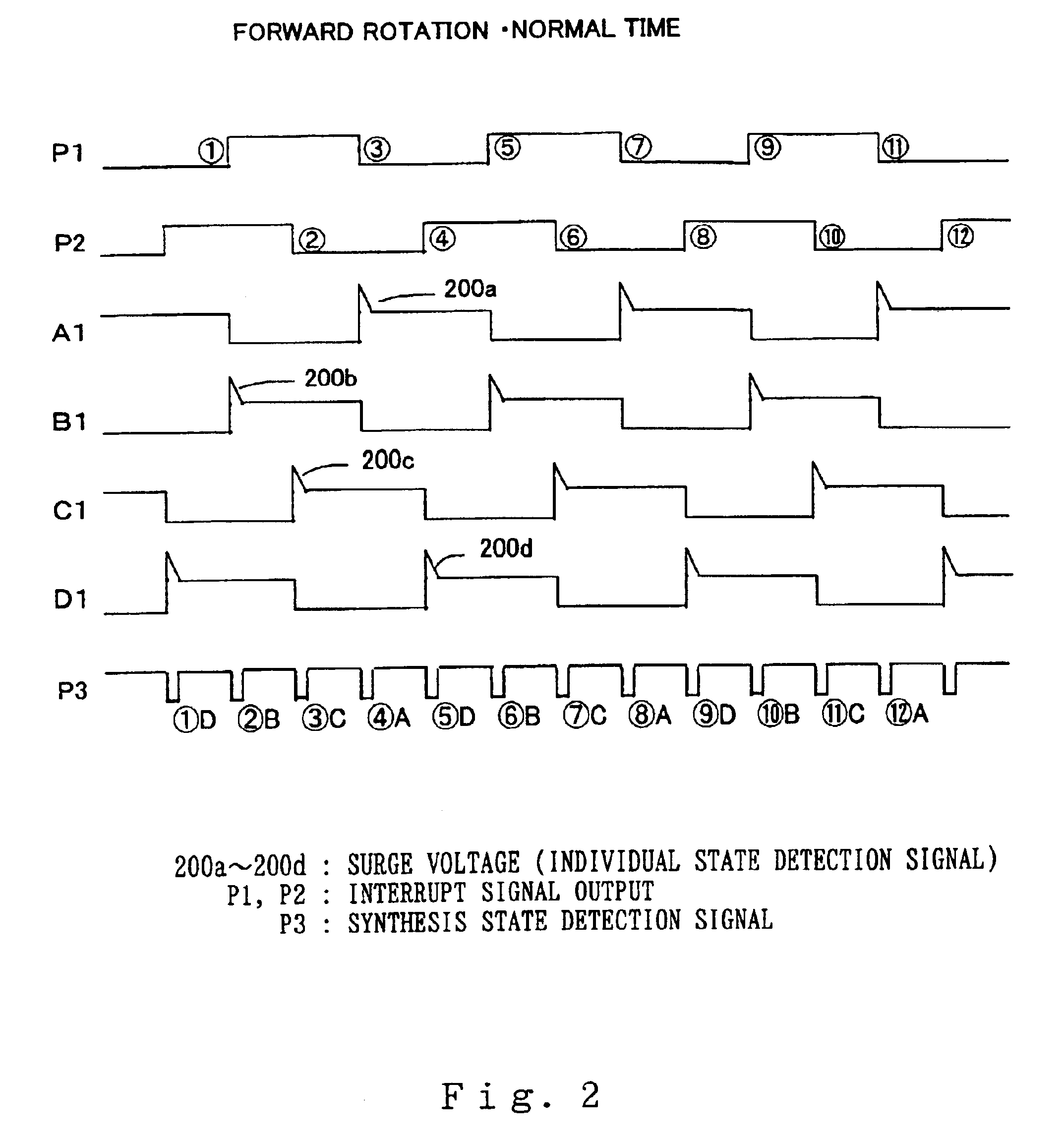
In the first embodiment according to the invention arranged as shown in FIG. 1, operation thereof is described first with reference to a time chart of the forward rotational operation of the stepping motor 101a shown in FIG. 2. Referring to FIG. 2, a rising edge of the interrupt signal output P1 from the microprocessor 110a is indicated by numerals 159, and a falling edge thereof is indicated by numerals 3711. Further, a rising edge of the interrupt signal output P2 from the microprocessor 101a is indicated by numerals 4812, and a falling edge thereof is indicated by numerals 2610. At a point of the rising edge 159 of the interrupt signal output P1, the interrupt signal output P2 is kept at a level of "H": while at a point of the falling edge 3711 of the interrupt signal output P1, the interrupt signal output P2 is kept at a level of "L". This state of outputs shows a forward rotation state.
Numerals A1, B1, C1, D1 in FIG. 2 indicate voltage wave forms of the collector terminals of t...
embodiment 2
1. Detailed Description of Constitution According to Embodiment 2
FIG. 7 is a block diagram showing another embodiment according to the invention. Differences from the first embodiment of FIG. 1 are primarily described below. With reference to FIG. 7, numeral 100b designates an abnormality detector that contains therein a microprocessor 110b, and controls driving a stepping motor 101b connected outside. Numeral 102a designates a rotor of the mentioned stepping motor 101b. In this second embodiment, the return-detecting switch 102d shown in FIG. 1 is not provided. Moreover, the power supply relay 106a shown in FIG. 1 is not used, and the abnormality detector 100b is directly power-fed from the on-vehicle battery 104, or fed via the power supply switch 105.
As for the internal constitution of the abnormality detector 114b, the collector terminals of the open / close elements 114a, 114b, 114c, 114d are connected to the connector terminals A1, B1, C1, D1 and drive the magnetic field coils 1...
PUM
 Abstract
Description
Claims
Application Information
 - R&D
- Intellectual Property
- Life Sciences
- Materials
- Tech Scout
- Unparalleled Data Quality
- Higher Quality Content
- 60% Fewer Hallucinations
Browse by: Latest US Patents, China's latest patents, Technical Efficacy Thesaurus, Application Domain, Technology Topic, Popular Technical Reports.
© 2025 PatSnap. All rights reserved.Legal|Privacy policy|Modern Slavery Act Transparency Statement|Sitemap|About US| Contact US: help@patsnap.com


