X-ray topographic system

a topographic system and x-ray technology, applied in the direction of material analysis using wave/particle radiation, semiconductor/solid-state device testing/measurement, instruments, etc., can solve the problems of large camera system size, limited wafer size which can be examined, and prior art processes have suffered

Inactive Publication Date: 2004-08-24
BRUKER TECH LTD
View PDF16 Cites 23 Cited by
  • Summary
  • Abstract
  • Description
  • Claims
  • Application Information

AI Technical Summary

Benefits of technology

Other features and advantages of the present invention will be apparent from the following description and from the appended claims.

Problems solved by technology

Prior art processes have suffered from a number of disadvantages, including the large size of the camera system, limitations on the size of the wafer which can be examined, and long processing times (typically about one hour for an 8" or 200 mm wafer).

Method used


Image

  • X-ray topographic system
  • X-ray topographic system
  • X-ray topographic system

Examples


Embodiment Construction

Embodiments of the invention will now be described, by way of example only, with reference to the drawings, in which:

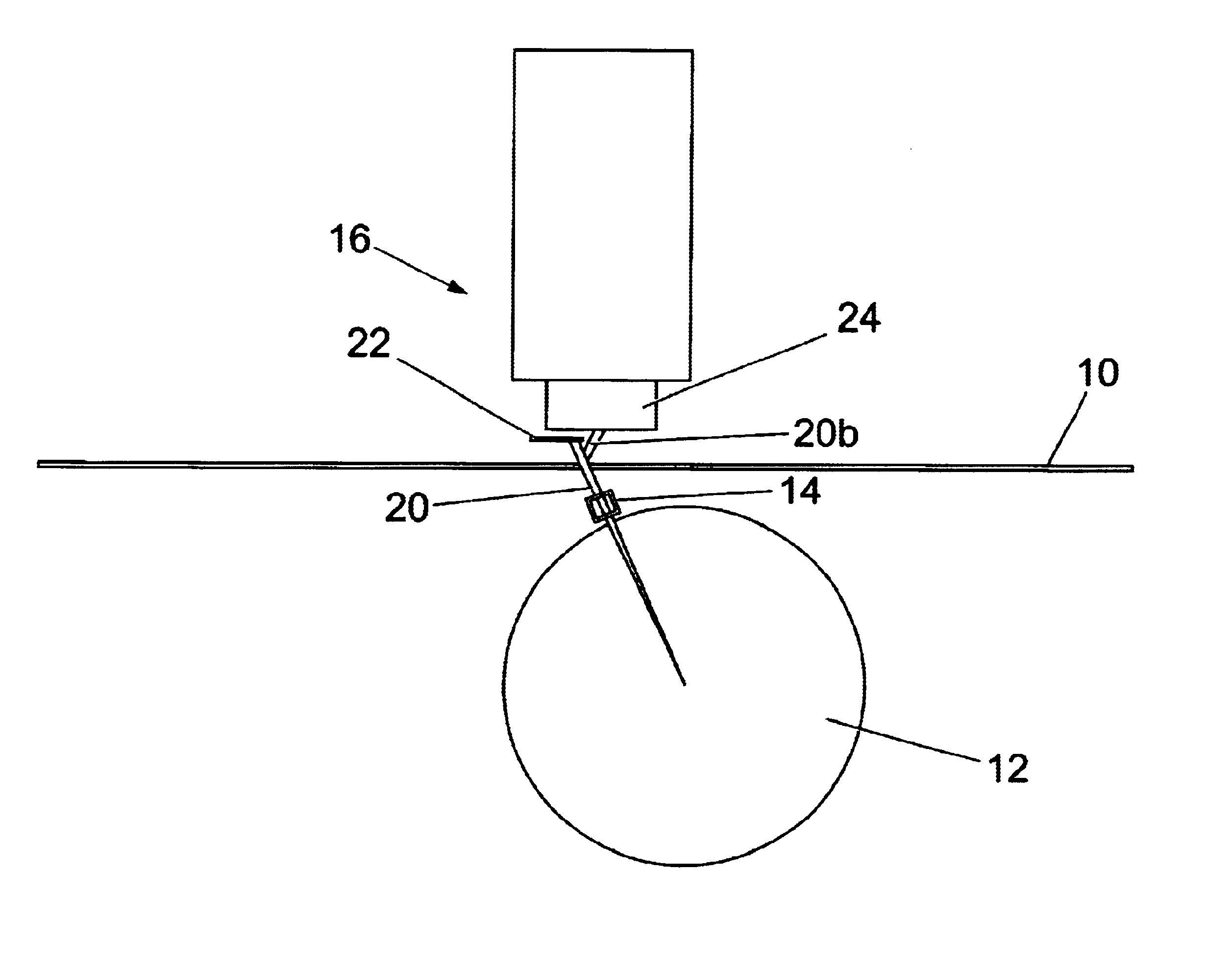
FIG. 1 is a schematic side view illustrating one system embodying the invention;

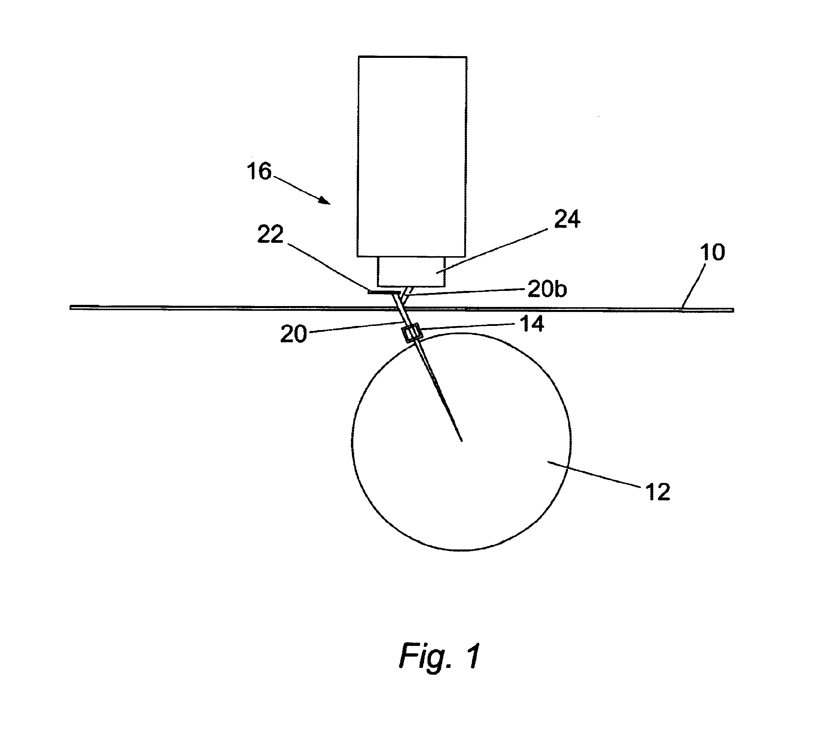
FIG. 2 illustrates the operation of the system of FIG. 1;

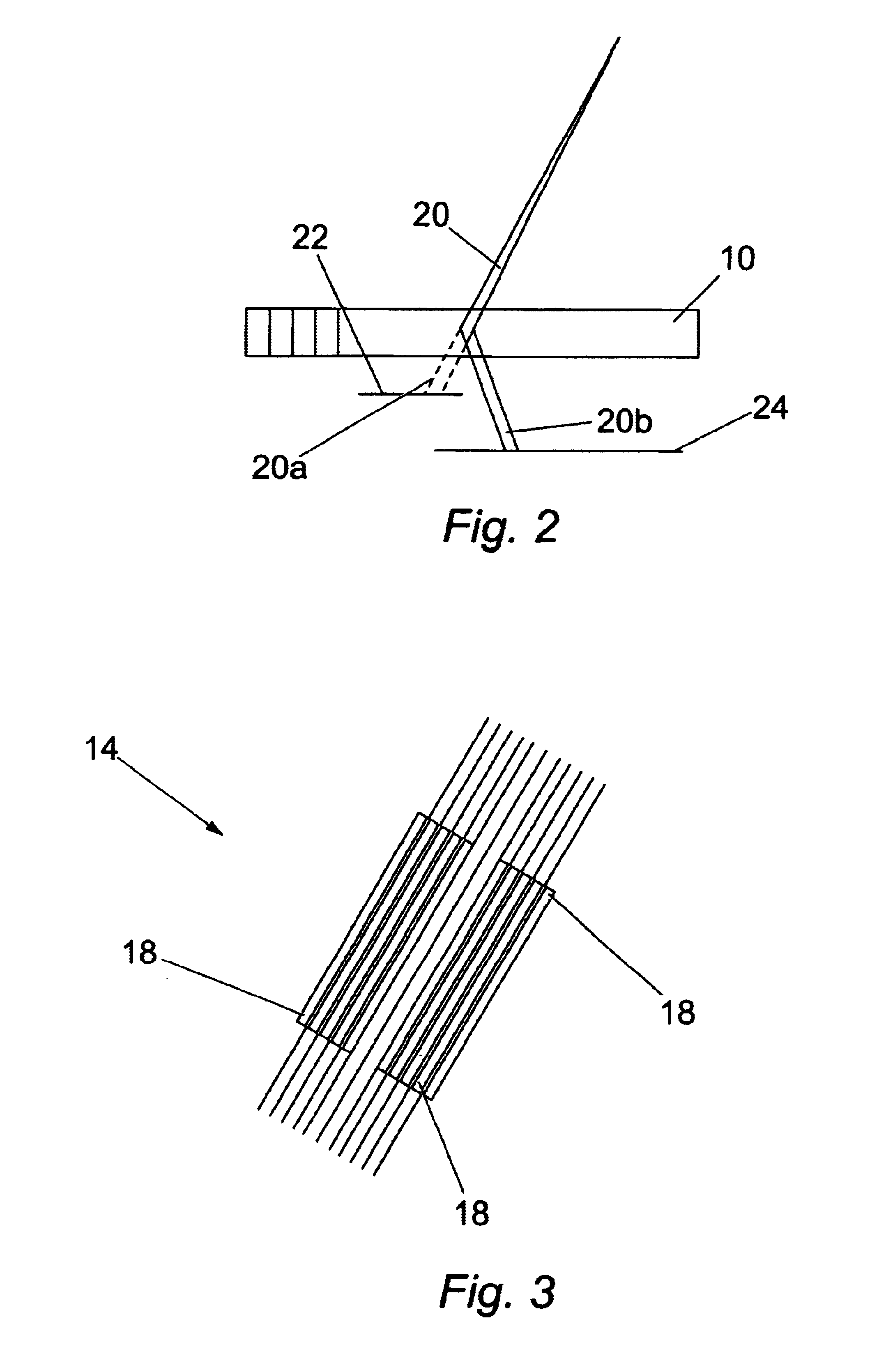
FIG. 3 shows one component of FIG. 1 in greater detail;

FIG. 4 is a schematic representation of an apparatus incorporating the system of FIG. 1;

FIG. 5 illustrates an alternative form of apparatus;

FIG. 6 illustrates a modified system without an x-ray optic;

FIG. 7 is an example of an image obtained by a system embodying the invention;

FIG. 8 is a flow chart of an algorithm used in one form of the invention;

FIG. 9 illustrates geometric coordinates used in combining images;

FIG. 10 is a flow chart of an algorithm used in combining images; and

FIGS. 11 and 12 are examples of combined images.

EMBODIMENT OF WAFER INSPECTION SYSTEM

The embodiment of FIGS. 1 to 3 is particularly suitable for slip band detection in Si wafers up to 300 mm diameter.

Re...


PUM

PropertyMeasurementUnit
thickaaaaaaaaaa
spot sizeaaaaaaaaaa
sizeaaaaaaaaaa

Abstract

An X-ray topographic system comprises an X-ray generator producing a beam of X-rays impinging on a limited area of a sample such as a silicon wafer. A solid state detector is positioned to intercept the beam after transmission through or reflection from the sample. The detector has an array of pixels matching the beam area to produce a digital image of said limited area. Relative stepping motion between the X-ray generator and the sample produces a series of digital images which are combined together. In optional embodiments, an X-ray optic is interposed to produce a parallel beam to avoid image doubling, or the effect of image doubling is removed by software.

Description

This invention relates to an X-ray topographic system for use in examining crystal structures, for example silicon single-crystal wafers or boules for use in the production of semiconductors.BACKGROUND TO THE INVENTIONIt is known to examine, for example, silicon wafers by means of X-rays to detect flaws such as slip bands which are nucleated during the rapid thermal annealing process. Such examination has hitherto been carried out by means of a Lang camera making an exposure on film. Prior art processes have suffered from a number of disadvantages, including the large size of the camera system, limitations on the size of the wafer which can be examined, and long processing times (typically about one hour for an 8" or 200 mm wafer).One object of the present invention is to provide an X-ray topographic system which is capable of examining large samples, typically up to 300 mm diameter, and carrying out examinations rapidly, typically 5 to 15 minutes.Accordingly, the present invention ...

Claims


Application Information

Patent Timeline
Patent Type & Authority Patents(United States)
IPC IPC(8): G01N23/20G01N23/207G01N23/203G01N23/04H01L21/66
CPCG01N23/207
Inventor BOWEN, DAVID KEITHWORMINGTON, MATTHEWPINA, LADISLAVFEICHTINGER, PETRA
Owner BRUKER TECH LTD
Why Eureka
Try Eureka