
Radiation image capturing apparatus and method of detecting malfunction of radiation image capturing apparatus

Inactive Publication Date: 2008-09-18
FUJIFILM CORP
View PDF2 Cites 16 Cited by
  • Summary
  • Abstract
  • Description
  • Claims
  • Application Information

AI Technical Summary

Benefits of technology

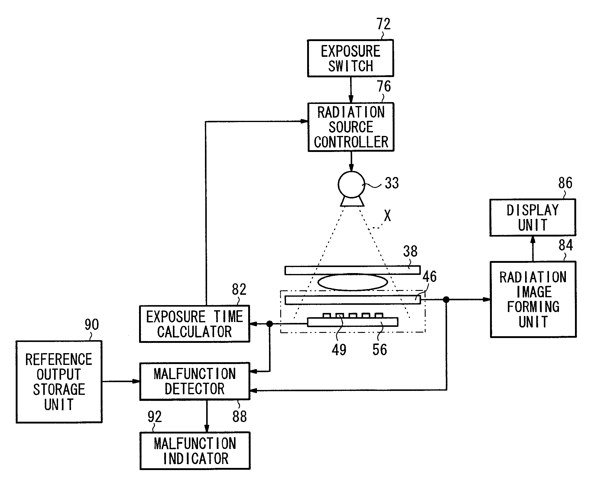
[0010]According to an aspect of the present invention, a radiation image capturing apparatus includes a malfunction detector for comparing output signals generated by a radiation image generating means and a radiation dose information detector based on a radiation emitted from a radiation source, with stored respective reference output ranges, in order to detect a malfunction of any of the radiation image generating means, the radiation dose information detector, or the radiation source. It is possible to detect a malfunction of any of the radiation image generating means, the radiation dose information detector, or the radiation source, easily and inexpensively without the need for a separate instrument such as a radiation dosimeter or the like.

Problems solved by technology

Radiation detectors, including the solid-state detector and the AEC sensor used in the radiation image capturing apparatus, may possibly suffer from sensitivity malfunctions characterized by fluctuations of an output value thereof (an output signal level or an output current value) with respect to an expected value.
Alternatively, the radiation detectors may have normal sensitivity, but the radiation source may possibly suffer from output malfunctions.
However, if an existing radiation image capturing apparatus does not incorporate such a radiation dosimeter therein, then the radiation image capturing apparatus will require extra expenditures of expense and time in order to connect and adjust the added radiation dosimeter.
A radiation image capturing apparatus with a built-in radiation dosimeter, however, is costly due to the presence of the built-in radiation dosimeter.

Method used


Image

  • Radiation image capturing apparatus and method of detecting malfunction of radiation image capturing apparatus
  • Radiation image capturing apparatus and method of detecting malfunction of radiation image capturing apparatus
  • Radiation image capturing apparatus and method of detecting malfunction of radiation image capturing apparatus

Examples


Embodiment Construction

[0020]A radiation image capturing apparatus, and a method of detecting a malfunction in a radiation image capturing apparatus, according to preferred embodiments of the present invention shall be described in detail below with reference to the accompanying drawings.

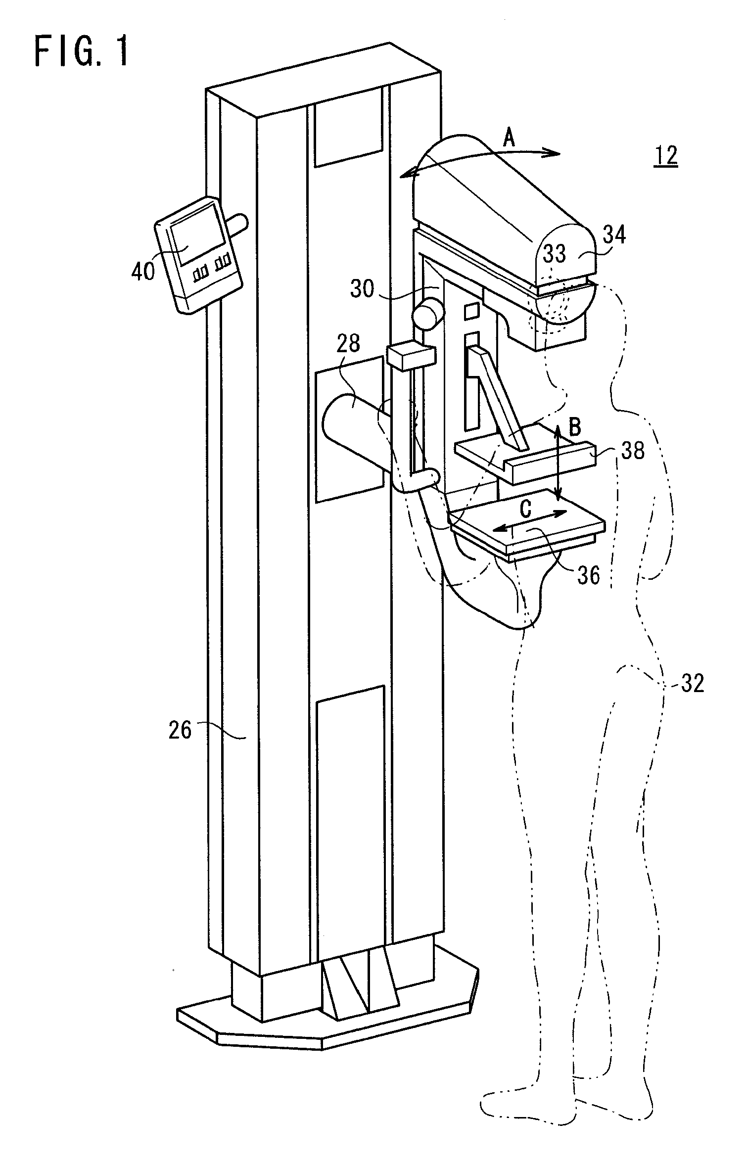
[0021]FIG. 1 shows in perspective a mammographic system 12 as an example of a radiation image capturing apparatus according to an embodiment of the present invention. Although a mammographic system 12 will be described below as exemplifying the radiation image capturing apparatus according to the embodiment of the present invention, the present invention is not limited to a mammographic system 12.

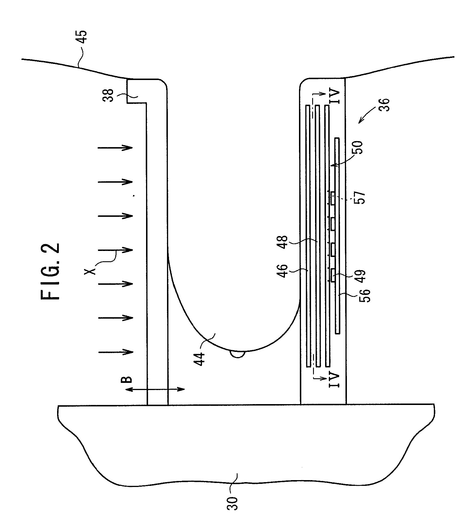
[0022]As shown in FIG. 1, the mammographic system 12 includes an upstanding base 26, a vertical arm 30 fixed to a horizontal swing shaft 28 disposed substantially centrally on the base 26, a radiation source housing unit 34 storing a radiation source 33 for applying radiation to a breast of a subject 32 to be imaged, and which is...


PUM


Abstract

A mammographic system as a radiation image capturing apparatus includes a radiation source for emitting radiation, a solid-state detector for detecting radiation emitted from the radiation source and generating a radiation image based on such radiation, AEC sensors for detecting a radiation dose emitted from the radiation source, a radiation source controller for controlling the dose emitted from the radiation source based on output signals from the AEC sensors, a reference output storage unit for storing reference output ranges defining respective ranges of reference output signals for the solid-state detector and the AEC sensors, and a malfunction detector for comparing output signals generated by the solid-state detector and the AEC sensors with the respective reference output ranges to detect a malfunction of the solid-state detector, the AEC sensors, or the radiation source.

Description

BACKGROUND OF THE INVENTION[0001]1. Field of the Invention[0002]The present invention relates to a radiation image capturing apparatus including a malfunction detecting means for detecting a malfunction of a radiation image generating means, a radiation dose information detector, or a radiation source. The present invention also relates to a method of detecting a malfunction of such a radiation image capturing apparatus.[0003]2. Description of the Related Art[0004]In the medical field, there have widely been used radiation image capturing apparatuses, which apply radiation emitted from a radiation source to a subject. Such apparatus then detect the radiation that has passed through the subject with a radiation detector, and record radiation image information based on the detected radiation.[0005]The radiation image capturing apparatuses of the type described above are required to achieve a good level of radiation image quality, while minimizing the radiation dose applied to the subj...

Claims


Application Information

Patent Timeline
IPC IPC(8): G01J1/42
CPCA61B6/107A61B6/4233G01T1/247A61B6/586G01T1/026A61B6/502
Inventor NAKAYAMA, HIROKI
Owner FUJIFILM CORP
Learn More