Drum washing machine

a drum and drum technology, applied in spin dryers, mechanical devices, rotating bodies, etc., can solve the problems of noise, vibration of outer tanks, and inability to provide water storage boxes on the front end surface of drums, and in some cases, insufficient compensation of eccentric loads

Inactive Publication Date: 2004-08-31
SANYO ELECTRIC CO LTD
View PDF27 Cites 39 Cited by
  • Summary
  • Abstract
  • Description
  • Claims
  • Application Information

AI Technical Summary

Benefits of technology

Still another object of the present invention is to provide a drum washing machine that is convenient to use and produces a quiet operating sound.
Consequently, the washing is unevenly distributed at a position, offset toward the opposite side of the position where the drum rotating motor is provided, in the drum, thereby making it possible to set off, even when the eccentric load is produced in the drum, the eccentric load by the function of the water storage balancer. Accordingly, it is possible to satisfactorily restrain the generation of vibration caused by the uneven distribution of the washing and noise caused by the vibration.
When such construction is added, the washing is unevenly distributed at the position, offset toward the side of the position where the drum rotating motor is provided, in the drum, thereby making it possible to set off, even when the eccentric load is produced in the drum, the eccentric load by the function of the motor-side water storage balancer. Accordingly, it is possible to effectively restrain the generation of vibration caused by the uneven distribution of the washing and noise caused by the vibration.
When such construction is added, the fluid balancer is provided, thereby making it possible to restrain vibration which cannot be restrained depending on the function of the water storage balancer and vibration caused by an eccentric load which is so small that it need not be compensated for by making balance adjustment using the water storage balancer. Accordingly, it is possible to effectively restrain the vibration and noise caused by the vibration.
The washing machine according to the present invention may further comprise an outer tank (2) elastically supported by an elastic member (3F, 3B) and accommodating the drum so as to be rotatable. Further, the elastic member maybe a damper (3F, 3B) for supporting a portion, near the drum rotating motor, of the outer tank from below. In this case, the eccentric load due to the uneven distribution of the washing is almost produced on the opposite side of the drum rotating motor with respect to the position where the outer tank is supported by the damper. Accordingly, the present invention is particularly effective in restraining the vibration caused by the eccentric load and the noise caused by the vibration.

Problems solved by technology

One of problems of the drum washing machine is that when the drum is rotated at high speed with the washing unevenly distributed inside the drum at the time of spin-drying, an eccentric load is produced inside the drum, which causes vibration of the outer tank and noise caused by the vibration.
Accordingly, the water storage box cannot be provided on the front end surface of the drum, but is inevitably provided on the rear end surface of the drum.
In this case, even if the amount of water in the water storage box provided on the rear end surface of the drum is adjusted, the eccentric load cannot, in some cases, be sufficiently compensated for.

Method used


Image

  • Drum washing machine
  • Drum washing machine
  • Drum washing machine

Examples


Embodiment Construction

An embodiment of the present invention will be described in detail with reference to the accompanying drawings.

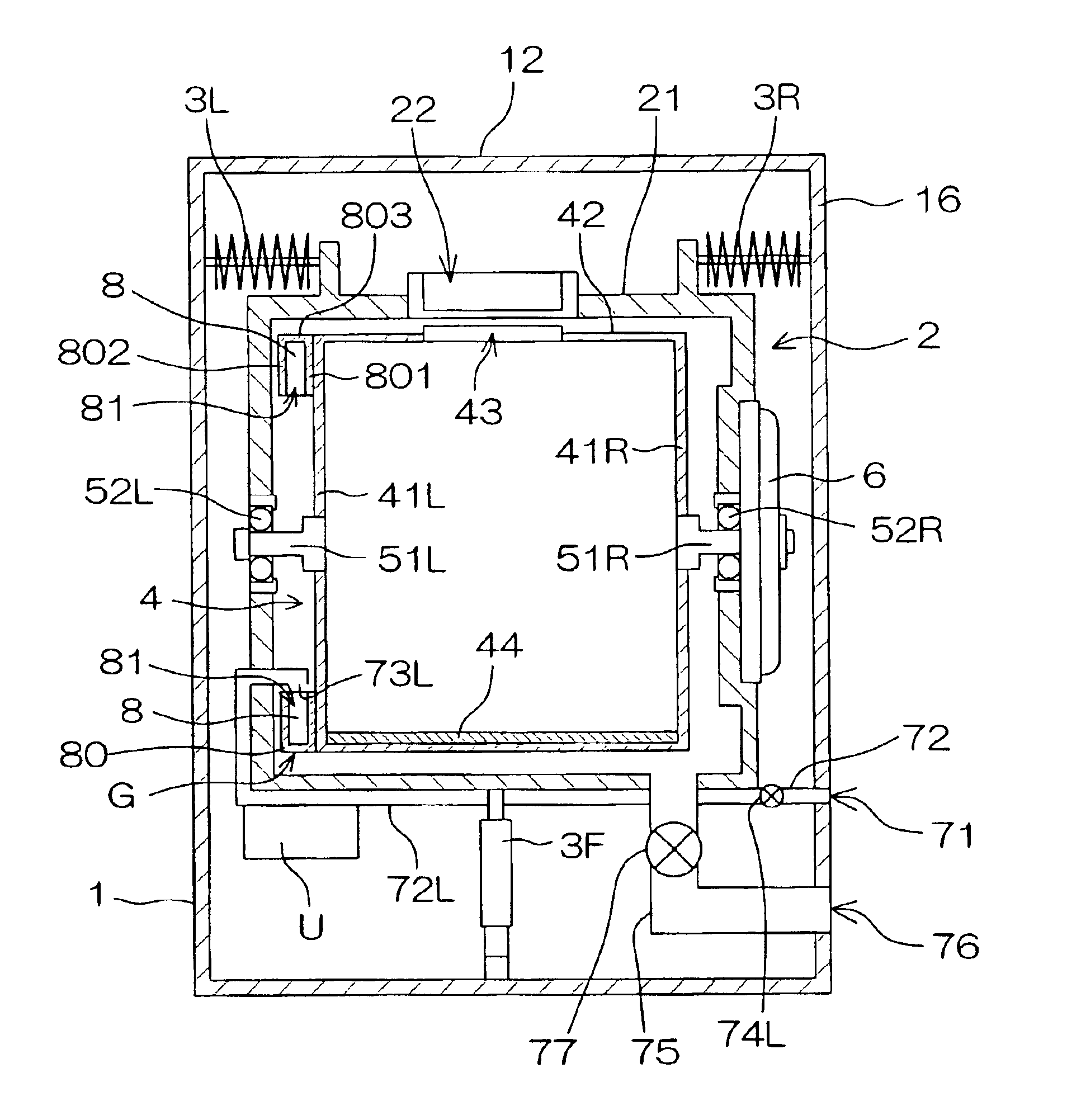
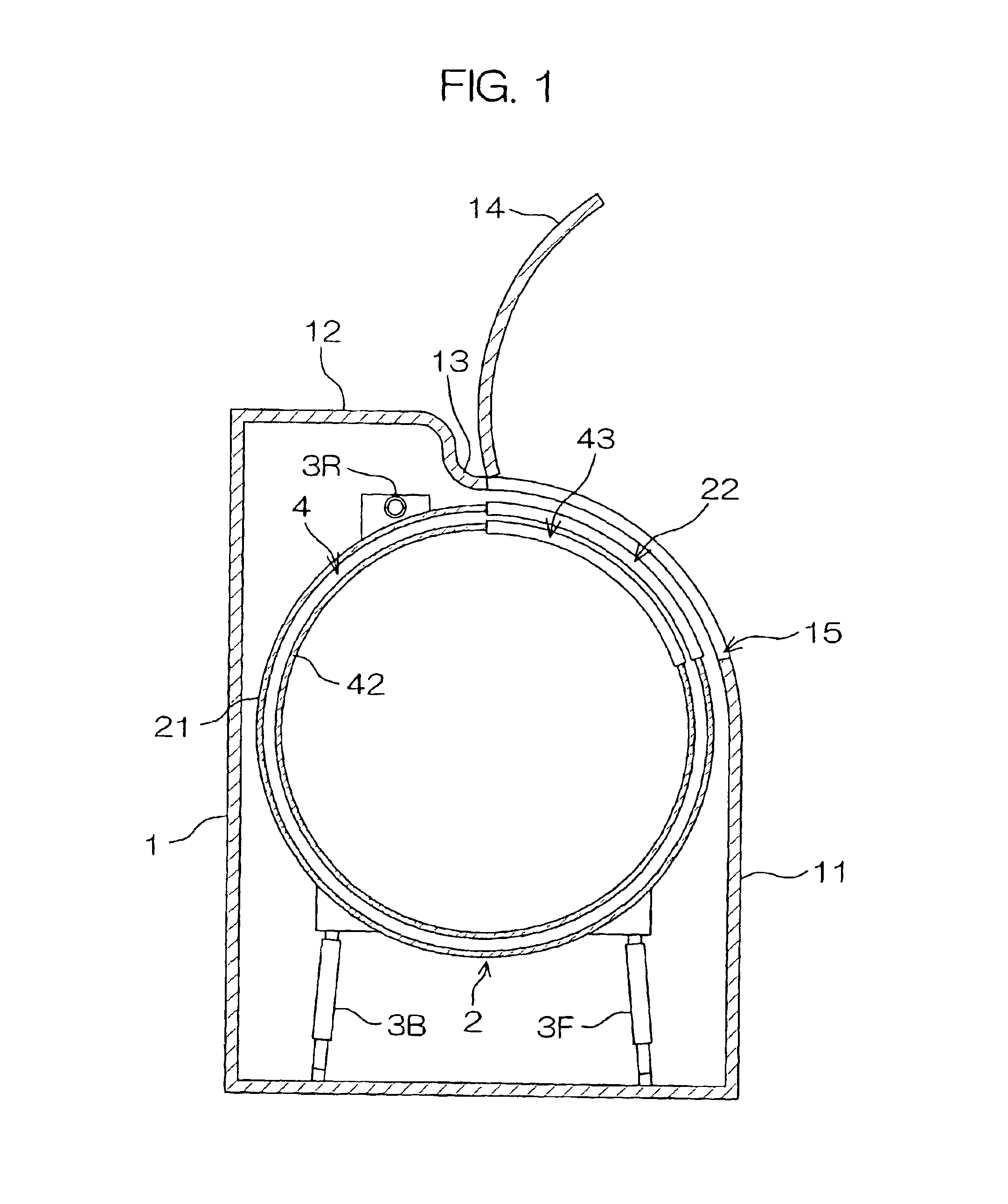
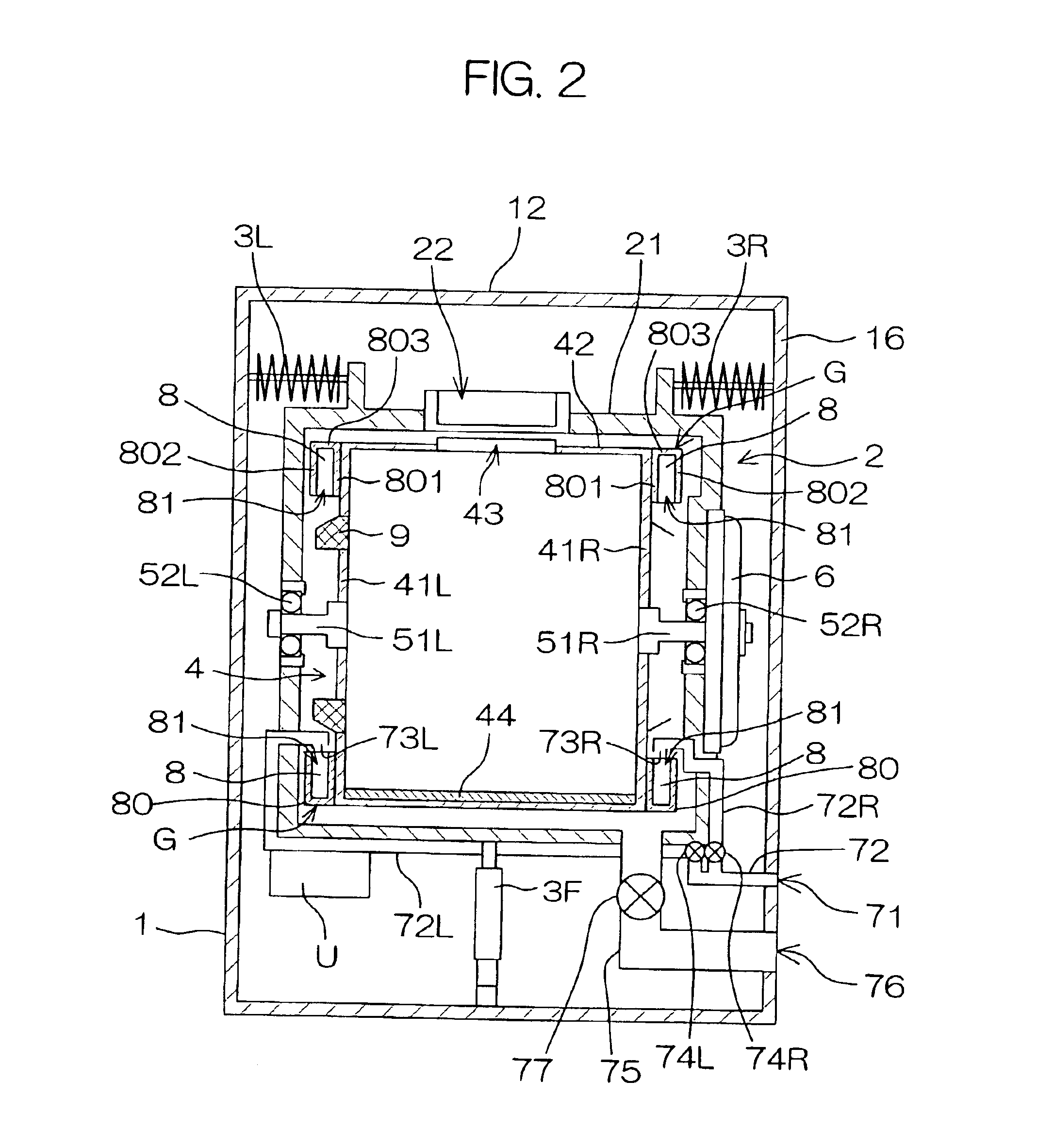
FIGS. 1 and 2 are longitudinal sectional views showing the overall construction of a drum washing machine according to an embodiment of the present invention, where FIG. 1 illustrates a cross section of the drum washing machine taken along a vertical surface in a front-and-back direction, and FIG. 2 illustrate a cross section of the drum washing machine taken along a vertical surface in a right-and-left direction.

A case 1 constituting the appearance of the drum washing machine is formed in such a size that the drum washing machine can be set up in a washing machine pan. Further, the drum washing machine is so designed that the height thereof in a case where it is set up on the floor (the height from the floor to an upper surface of the case 1)is approximately to the waste waist of a user.

An outer tank 2 in a hollow cylindrical shape is provided with its end surfaces extendi...


PUM


Abstract

A drum washing machine according to the present invention restrains vibration and noise at the time of spin-drying. For this purpose, a drum 4 is supported so as to be rotatable by rotating shafts 51L and 51R respectively extending in an approximately horizontal direction outward from its end surface walls 41L and 41R. Water storage balancers G are respectively attached to the end surface walls 41L and 41R of the drum 4, and a fluid balancer 9 is further attached to the end surface wall 41L.

Description

This application is based on an application No. 2001-291715 filed in Japan, the content of which is incorporated hereinto by reference.1. Field of the InventionThe present invention relates to a washing machine comprising a centrifugal spin-drying function, and particularly, to a drum washing machine having a drum that rotates around its approximately horizontal axis.2. Description of Related ArtA drum washing machine comprises a cylindrical drum that rotates for washing and spin-drying with the washing put therein. The drum is provided with its end surfaces extending in a front-and-back direction inside a cylindrical outer tank. A rotating shaft extending in an approximately horizontal direction is connected to the rear end surface of the drum. The rotating shaft is received in the outer tank so as to be rotatable, to project toward the back of the outer tank. A motor is coupled to a rear end of the rotating shaft using a DD (Direct Drive) system, for example. The drum is rotated a...

Claims


Application Information

Patent Timeline
Patent Type & Authority Patents(United States)
IPC IPC(8): D06F37/22D06F37/20D06F37/04D06F49/02D06F39/08
CPCD06F37/225Y10T74/2109D06F37/04
Inventor YOKOI, YASUHIKOYAMAMOTO, HIROSHISONODA, YASUAKIKINOUCHI, TAKAO
Owner SANYO ELECTRIC CO LTD
Why Eureka
Try Eureka