Clamping apparatus with a clamping chuck and a work piece carrier releasably connectable thereto

a technology of work piece carrier and clamping chuck, which is applied in the direction of chucks, manufacturing tools, metal-working machine components, etc., can solve the problems of inability to provide a z-reference or z-direction stop member in the area, damage to elastically resilient areas, and lasting weakened clamping chucks

Inactive Publication Date: 2004-10-05
EROWA
View PDF11 Cites 56 Cited by
  • Summary
  • Abstract
  • Description
  • Claims
  • Application Information

AI Technical Summary

Benefits of technology

It is an object of the invention to provide a clamping apparatus with a clamping chuck and a work piece carrier releasably connected thereto whose clamping chuck is particularly suitable for palletizing systems, whereby the individual clamping chuck shall be very robust and rigid.
It is a still further object of the invention to provide a clamping apparatus with a clamping chuck and a work piece carrier releasably connected thereto in which a movement of the clamping pin and, thereby, the work piece carrier in Z-direction is possible after the clamping pin has been aligned in X- and / or Y-direction, without the need to provide separate elastically resilient means.
Thus, the basic idea of the invention may be seen in the fact that the clamping pin is designed in such a way that it can align itself without clearance in X- and / or Y-direction upon insertion into the opening of the clamping chuck without the work piece carrier resting on the clamping chuck. In other words, during that aligning of the clamping pin, a small gap remains between the bottom surface of the work piece carrier and the top surface of the clamping chuck. This gap is removed when the clamping pin is further pulled in into the opening of the clamping chuck by means of the clamping mechanism, whereby the material elasticity of the clamping pin and / or of the region of the clamping chuck around the central opening is used for that purpose. Thereby, the work piece carrier is moved in Z-direction towards the clamping chuck until its flat bottom surface rests on the Z-direction stop member constituted by the corresponding surface areas on top of the clamping chuck. In this way, the provision of means that are elastically resilient in Z-direction can be totally avoided.

Problems solved by technology

However, in the case of clamping apparatus adapted to receive large and heavy work piece carriers, the clamping chuck is lastingly weakened by the provision of such a cutout.
Moreover, it is not possible to provide a Z-reference or a Z-direction stop member in the area around the above mentioned cutout since the clamping apparatus is too resilient in Z-direction in that area.
Finally, there is a danger that the elastically resilient area is damaged upon inserting the clamping pin into the clamping chuck because the elastically resilient area cannot bear high loads neither in axial nor in radial directions.
It is understood that such a clamping apparatus is not at all suitable for attaching a work piece holder to the working spindle of a machine tool in a highly precise and repeatable manner.

Method used


Image

  • Clamping apparatus with a clamping chuck and a work piece carrier releasably connectable thereto
  • Clamping apparatus with a clamping chuck and a work piece carrier releasably connectable thereto
  • Clamping apparatus with a clamping chuck and a work piece carrier releasably connectable thereto

Examples


Embodiment Construction

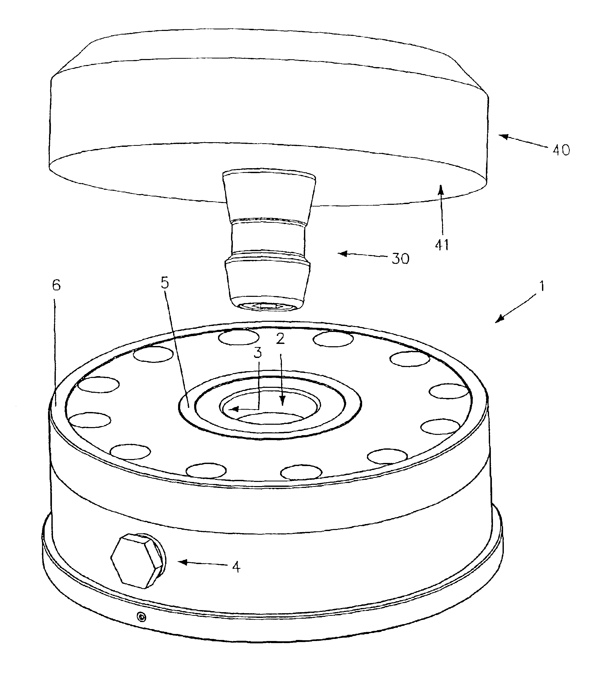
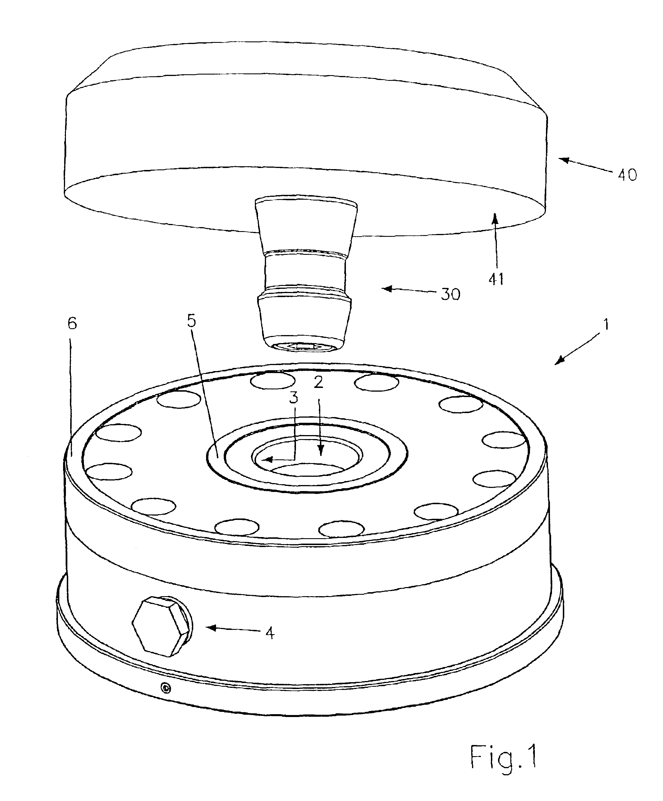
FIG. 1 shows a perspective view of a schematically illustrated clamping apparatus. The clamping apparatus comprises a clamping chuck generally designated by reference numeral 1 and a work piece carrier generally designated by reference numeral 40. The work piece carrier 40 is provided with a clamping pin 30 by means of which the work piece carrier 40 can be fixed to the clamping chuck 1. Such a clamping apparatus is preferably and particularly used in positionally exactly defined clamping of a work piece in the working area of a machine tool (not shown). Thereby, as it is the case in the present example, the work piece carrier 40 can simultaneously be the work piece itself.

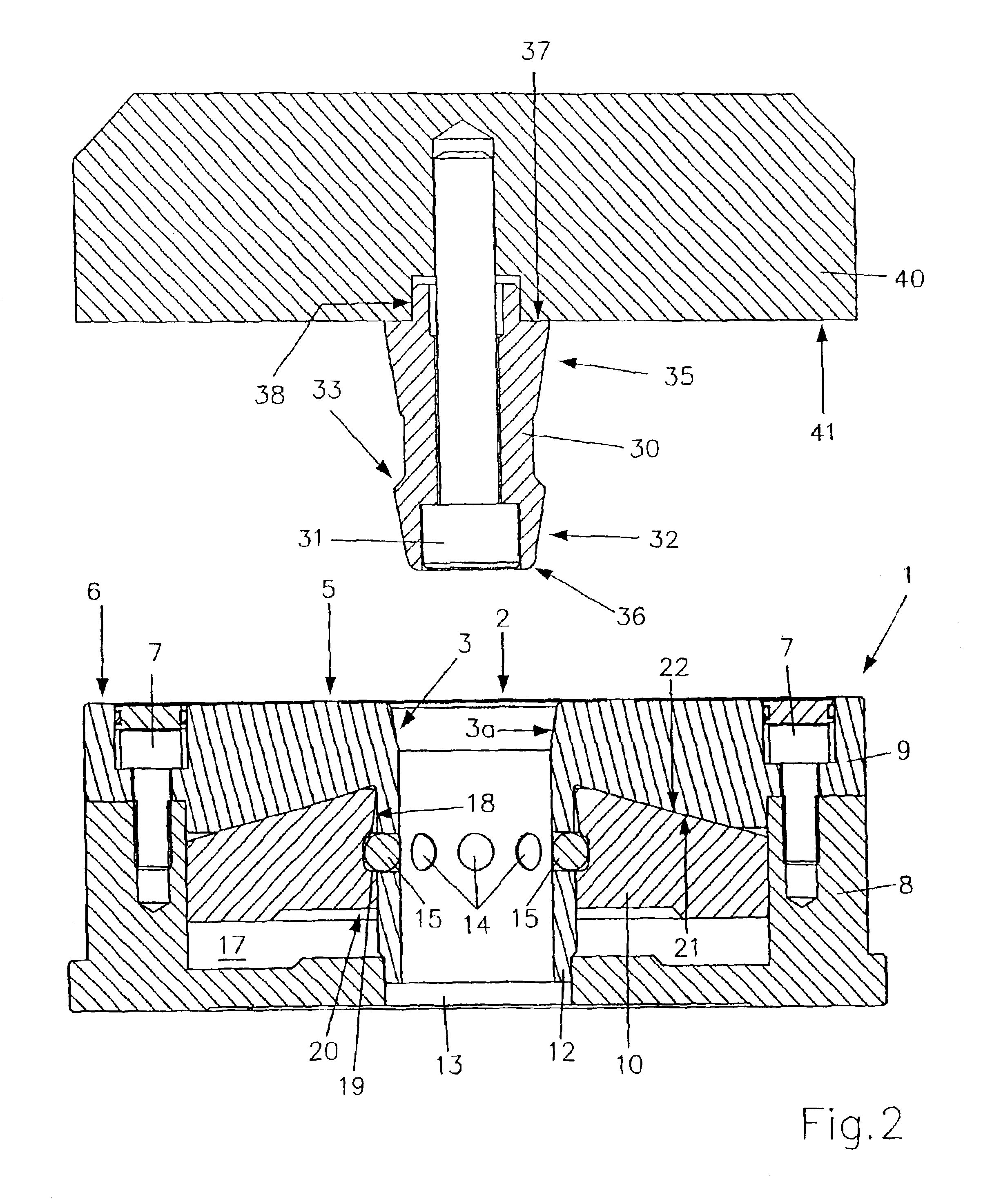
The clamping chuck 1, to be fixed to the machine tool by means known per se and not shown in the drawings, comprises a central opening 2 adapted to receive and fix the clamping pin 30 of the work piece carrier 40. The upper area of this opening 2 is designed as a conical inserting portion 3. The top surface of the...


PUM


Abstract

The clamping apparatus comprises a clamping chuck and a work piece carrier releasably connected thereto. The clamping chuck is provided with a central opening for receiving a clamping pin attached to the work piece carrier. The central opening of the clamping chuck has a conical inserting portion, and the clamping pin has at least one surface portion corresponding in shape to the conical inserting portion, or several surface portions for aligning the clamping pin in X- and / or Y-direction. The clamping chuck comprises a clamping mechanism for clamping the clamping pin. The top of the clamping chuck is provided with at least one surface portion serving as a Z-stop member. The clamping pin is dimensioned such that, prior to activating the clamping mechanism, a gap exists between the flat bottom surface of the work piece carrier and the surface portion of the clamping chuck serving as a Z-direction stop member. The clamping pin and / or the region around the central opening of the clamping chuck is / are adapted to be elastically deformed upon activation of the clamping mechanism to further pull in the clamping pin into the central opening and simultaneously the work piece carrier towards the surface portion serving as a Z-direction stop member until the flat bottom surface of the work piece carrier rests on the surface portion of the clamping chuck serving as a Z-direction stop member.

Description

The present invention refers to a clamping apparatus, comprising a clamping chuck and a work piece carrier adapted to be releasably connected to the clamping chuck, having a flat bottom surface and comprising a clamping pin protruding from the flat bottom surface. The clamping chuck comprises a central opening with a conical inserting portion for receiving the clamping pin of the work piece carrier. The clamping pin comprises at least one surface portion corresponding in shape to the shape of the conical inserting portion of the central opening for aligning the position of the clamping pin in X- and / or in Y-direction. Moreover, the clamping chuck is provided with a clamping mechanism for clampingly fixing the clamping pin of the work piece carrier in the central opening, and at least one surface portion serving as a Z-direction stop member.Such a clamping apparatus is preferably used for clamping work piece carriers equipped with one or several work pieces to be machined in the mach...

Claims


Application Information

Patent Timeline
Patent Type & Authority Patents(United States)
IPC IPC(8): B23Q7/14B23Q3/18B23Q1/00B23Q3/02B23B31/02B23Q3/00
CPCB23Q1/0072B23Q3/00
Inventor FRIES, KARL
Owner EROWA
Why Eureka
Try Eureka