Joint arrangement for a vehicle

a technology for vehicles and joints, applied in couplings, sealing bellows, sealing, etc., can solve the problems of increased tool wear, sealing bellows, and design restrictions, so as to reduce design restrictions and avoid grooves on wrench surfaces.

Active Publication Date: 2013-01-08
ZF FRIEDRICHSHAFEN AG
View PDF13 Cites 8 Cited by
  • Summary
  • Abstract
  • Description
  • Claims
  • Application Information

AI Technical Summary

Benefits of technology

[0011]Based on this state of the art, the basic object of the present invention is to perfect the joint arrangement mentioned in the introduction such that restrictions in design can be reduced and grooves in wrench surfaces can be avoided.
[0013]Since the gas-permeable connection opens according to the present invention into the interior space of the sealing bellows via the groove formed in the ring element, the provision of air passage grooves in a front surface of the joint, which front surface faces the rod, in a connection area between the joint and the rod can be avoided. Since, furthermore, the ring element forms a separate component arranged between the joint and the rod, it is likewise possible to avoid the use of a gas-permeable connection passing through a wrench surface. In particular, the ring element is arranged in the interior space defined by the sealing bellows.
[0017]The ring element may have an external diameter that is smaller than or equal to the external diameter of the joint housing. In particular, the ring element has the same external diameter as the rod. The risk that the sealing bellows will get caught at the ring and is damaged as a result can thus be reduced.

Problems solved by technology

The drawback of this solution is that the radial areas of the vent grooves extend in the front surface of the radial flange, which can also be used at the same time as a support surface when the joint is pressed together.
This surface is reduced by the vent grooves, which in turn leads to restrictions in design.
The drawback of the latter two solutions is that grooves combined with wrench surfaces form complicated contours, on which burs or increased tool wear may occur.
Furthermore, the sealing bellows according to JP 63-104173 may get caught at the ring element and become damaged as a result.

Method used


Image

  • Joint arrangement for a vehicle
  • Joint arrangement for a vehicle
  • Joint arrangement for a vehicle

Examples


Embodiment Construction

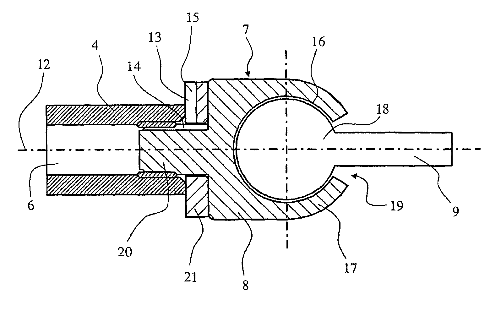
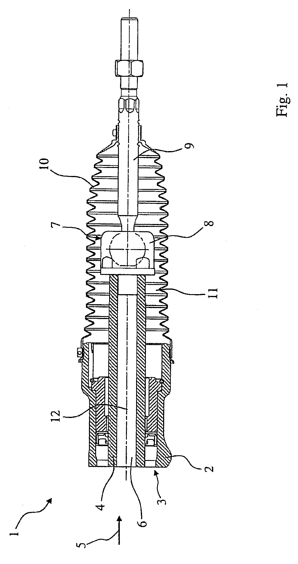
[0034]Referring to the drawings in particular, FIG. 1 shows a partially cut-away view of a rack-and-pinion steering 1, in which a toothed rack 4, which can be displaced by means of a steering gear 3 in the direction of arrow 5 and in the direction opposite arrow 5, is mounted in a housing 2 of a steering gear 3. The toothed rack 4 has a recess 6 and is connected at one end to a ball and socket joint 7. The ball and socket joint 7 has a joint housing 8 and a ball pivot 9, which is mounted rotatably and pivotably in same and which is seated with a joint ball 18 (see FIG. 2) in a recess 16 of the housing (see FIG. 2), which recess is formed in the joint housing 8, and is defined by a wall 17 (see FIG. 2) of the joint housing 8. The ball pivot 9 extends through an opening 19 provided in the ball and socket joint housing 8 (see FIG. 2) and protrudes from same, and a sealing bellows 10 is in contact with one end with the ball pivot 9 outside the ball and socket joint housing 8. With its o...


PUM


Abstract

Joint arrangement for a vehicle, with a joint (7), which has a joint housing (8) and a pivot pin (9) mounted movably in relation thereto; a rod (4), which has a cavity (6) and which is connected to the joint (7); a ring element arranged between the joint and the rod; a sealing bellows (10), which defines the interior space (11) and in which the joint (7) is arranged at least partially; and a gas-permeable connection (13), which connects the cavity (6) of the rod (4) to the interior space (11) of the sealing bellows (10), wherein at least part of the gas-permeable connection (13) is formed by at least one groove, which is formed on the ring element and opens into the interior space (11) of the sealing bellows (10).

Description

CROSS REFERENCE TO RELATED APPLICATIONS[0001]This application is a United States National Phase application of International Application PCT / DE 2007 / 000843 and claims the benefit of priority under 35 U.S.C. §119 of German Patent Application DE 10 2006 021 862.0 filed May 9, 2006, the entire contents of which are incorporated herein by reference.FIELD OF THE INVENTION[0002]The present invention pertains to a joint arrangement for a vehicle, with a joint, which has a joint housing and a pivot pin mounted therein movably relative to said joint housing; with a rod, which has a cavity and which is connected to the joint; with a ring element arranged between the joint and the rod; with a sealing bellows, which defines an interior space and in which the joint is arranged at least partially; and a connection, which is permeable to gases and connects the cavity of the rod to the interior space of the sealing bellows.BACKGROUND OF THE INVENTION[0003]Such joint arrangements are known from the ...

Claims


Application Information

Patent Timeline
Patent Type & Authority Patents(United States)
IPC IPC(8): F16C11/00
CPCB62D7/163F16C11/0671Y10T74/1967Y10T403/32631Y10T403/32729F16C2326/24F16C11/06F16C11/00B62D7/16
Inventor MAHLMANN, DIRKZIEBART, BENJAMIN
Owner ZF FRIEDRICHSHAFEN AG
Why Eureka
Try Eureka