
Joint arrangement for a vehicle
- Summary
- Abstract
- Description
- Claims
- Application Information
AI Technical Summary
Benefits of technology
Problems solved by technology
Method used
Image

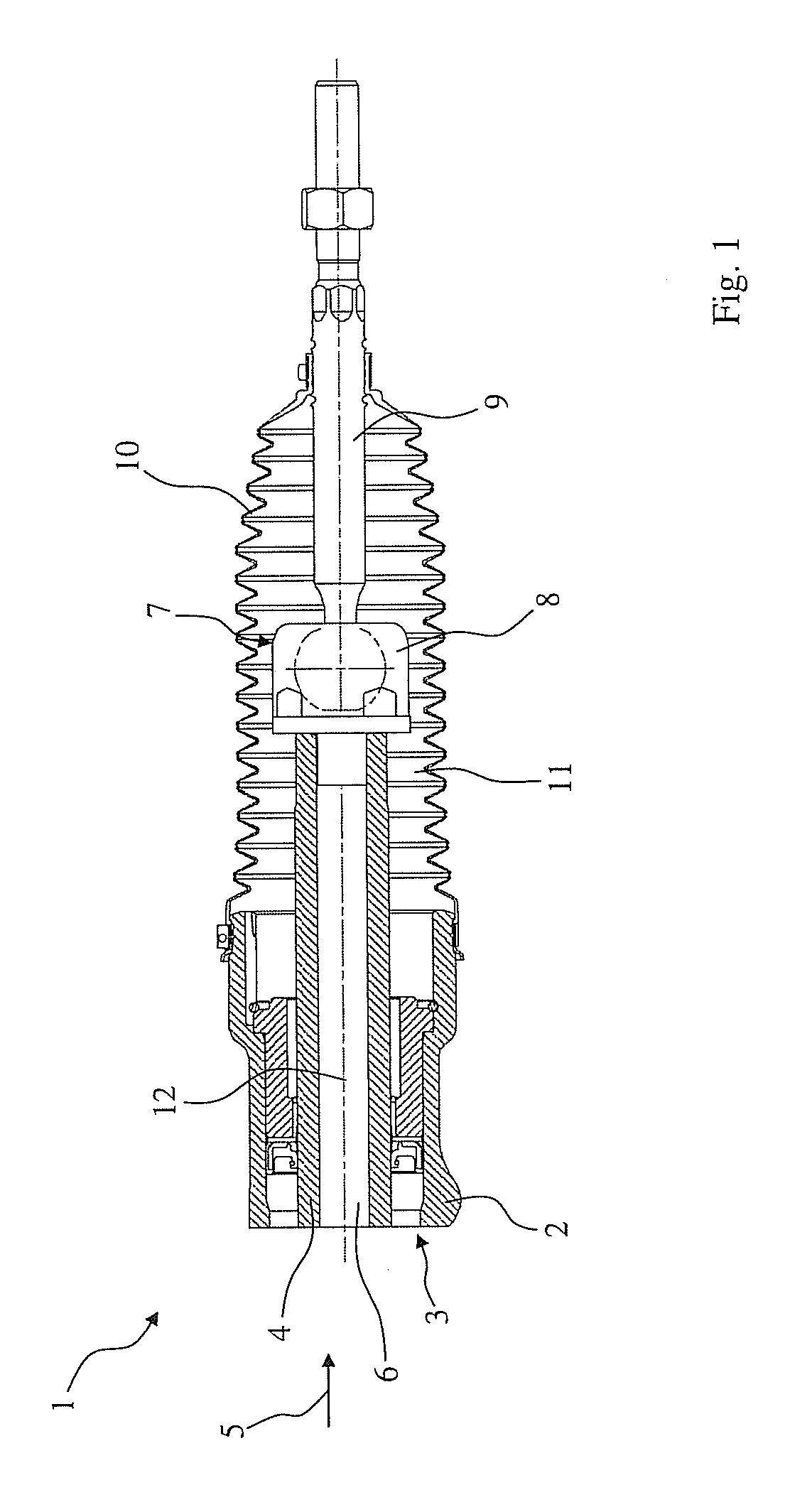
Examples
first embodiment
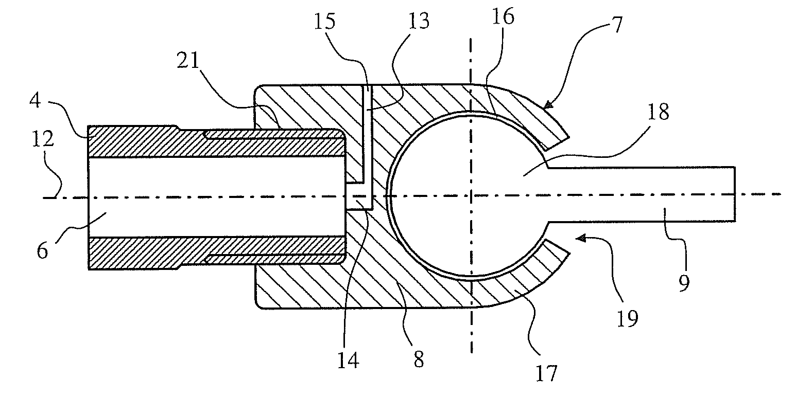
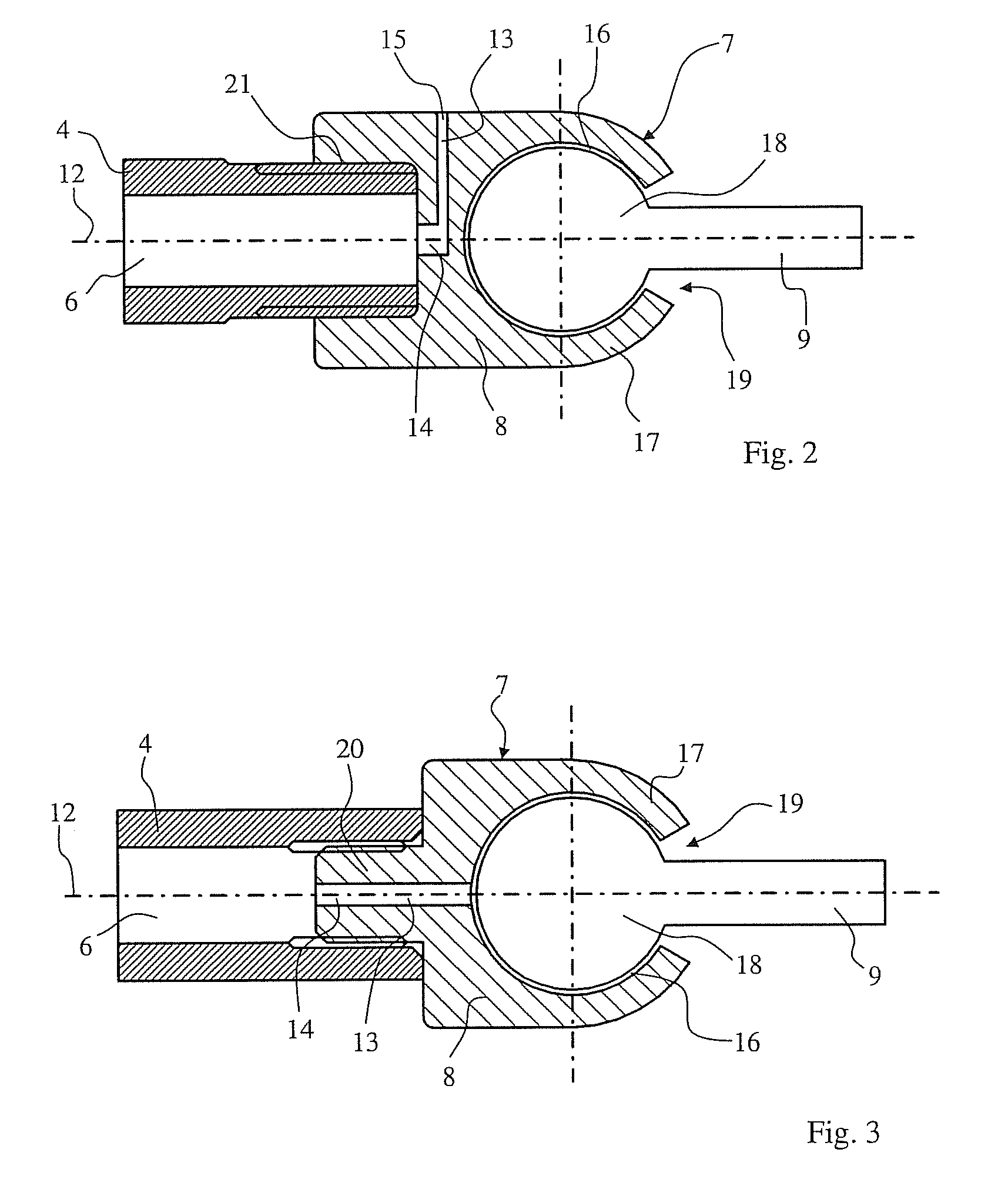
[0038]FIG. 2 shows the ball and socket joint 7 of the rack-and-pinion steering 1 according to the present invention in a sectional view, wherein cavity 6 is connected via the gas-permeable connection 13 to the interior space 11 of the sealing bellows 10, not shown here, in an air-permeable manner, where the interior space 11 is arranged outside the ball and socket joint housing 8. The gas-permeable connection 13 has an axial bore 14 formed in the ball and socket joint housing 8 and at least one radial bore 15, which is formed in the ball and socket joint housing 8 and passes over into the axial bore 14 within the ball and socket joint housing 8.
[0039]According to the first embodiment, the ball and socket joint housing 8 has, at its end facing the toothed rack 4, a pot-shaped recess 21 with an internal thread, which meshes with an end of the toothed rack 4, which said end faces the ball and socket joint housing 8. The toothed rack 4 and the ball and socket joint housing 8 are thus sc...
second embodiment
[0041]FIG. 3 shows a sectional view of the ball and socket joint 7 according to the present invention, wherein the gas-permeable connection 13 has an axial bore 14, which extends from cavity 6 through the joint housing 8 up to the recess 16. Bore 14 is connected to the interior space 11 of the sealing bellows 10, which is not shown here, in an air-permeable manner via the opening 19 and via intermediate spaces present in the recess 16 between the joint ball 18 and the wall 17.
[0042]The joint housing 8 has an axial pin 20, which is made especially in one piece with same, and which is provided with an external thread and extends into the interior space 6 of the toothed rack 4. An internal thread, which meshes with the external thread of pin 20, is formed in the area of the end of the toothed rack 4, which said end faces the ball and socket joint 7, on the inner wall of the toothed rack 4. The ball and socket joint housing 8 and the toothed rack 4 are thus screwed together.
[0043]FIG. 4...
fifth embodiment
[0046]FIG. 6 shows a sectional view of the ball and socket joint 7 according to the present invention, in which a recess 23, which is open towards the recess 16, is provided in the joint ball 18 of the ball pivot 9. Furthermore, at least one bore 24, which extends, starting from recess 23 through the ball pivot 9 up to the interior space 11 of the sealing bellows 10, not shown here, and thus forms an air-permeable connection between recess 23 and the interior space 11, is formed in the ball pivot 9. FIG. 6 shows two such bores 24. Since the recess 23 is open towards the recess 16, the cavity 6 is also connected to the interior space 11 in an air-permeable manner.
[0047]FIG. 7 shows a sectional view of the ball and socket joint 7 according to a sixth embodiment of the present invention, which is essentially identical to the second embodiment. However, contrary to this, a bearing shell 30, in which the joint ball 18 is mounted rotatably and pivotably, is arranged in the sixth embodimen...
PUM
 Abstract
Description
Claims
Application Information