
Controller for occupant restraint system

a technology for occupant restraints and controllers, which is applied in the direction of process control, process control, and pedestrian/occupant safety arrangements, etc. it can solve the problems of reducing the likelihood of serious injury for the occupants, system often does not consider other important, and system does not utilize multiple outputs to control both the airbag deployment and the sea

Inactive Publication Date: 2004-10-12
SIEMENS VDO AUTOMOTIVE CORP
View PDF25 Cites 32 Cited by
  • Summary
  • Abstract
  • Description
  • Claims
  • Application Information

AI Technical Summary

Problems solved by technology

If the vehicle decelerates suddenly, such as when a collision occurs, occupants will tend to continue to move forward due to inertial effects.
The deployment of the airbag and the utilization of the seat belt mechanisms decrease the likelihood of serious injury for the occupants.
These systems often do not consider other important factors such as child seat usage, seat belt usage, pre-crash vehicle data, crash severity data, braking data, etc. in determining whether or not to deploy the airbag.
Further these systems do not utilize multiple outputs to control both the airbag deployment and the seat belt mechanisms to minimize injury to the occupants.

Method used


Image

  • Controller for occupant restraint system
  • Controller for occupant restraint system
  • Controller for occupant restraint system

Examples


Embodiment Construction

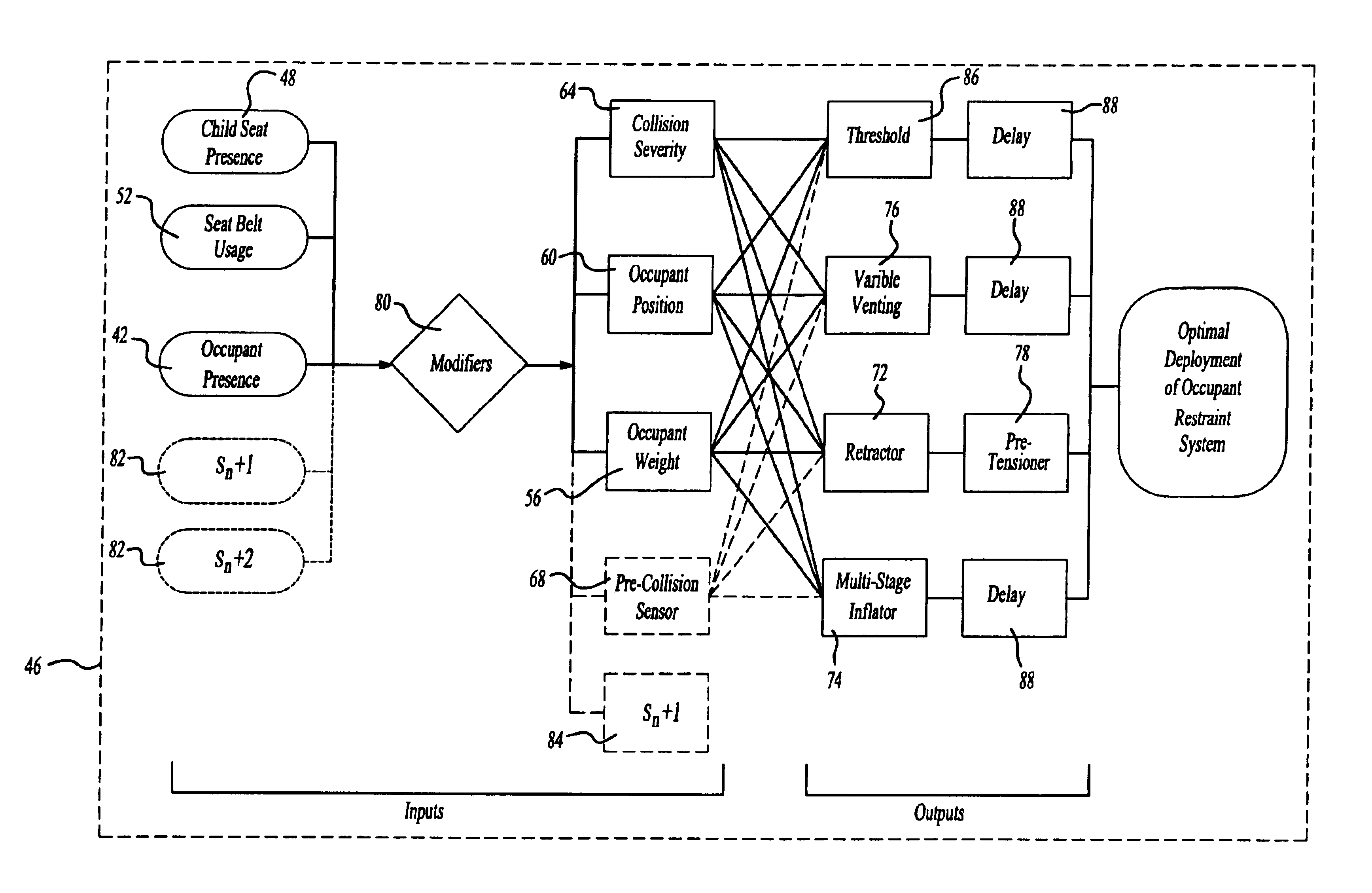
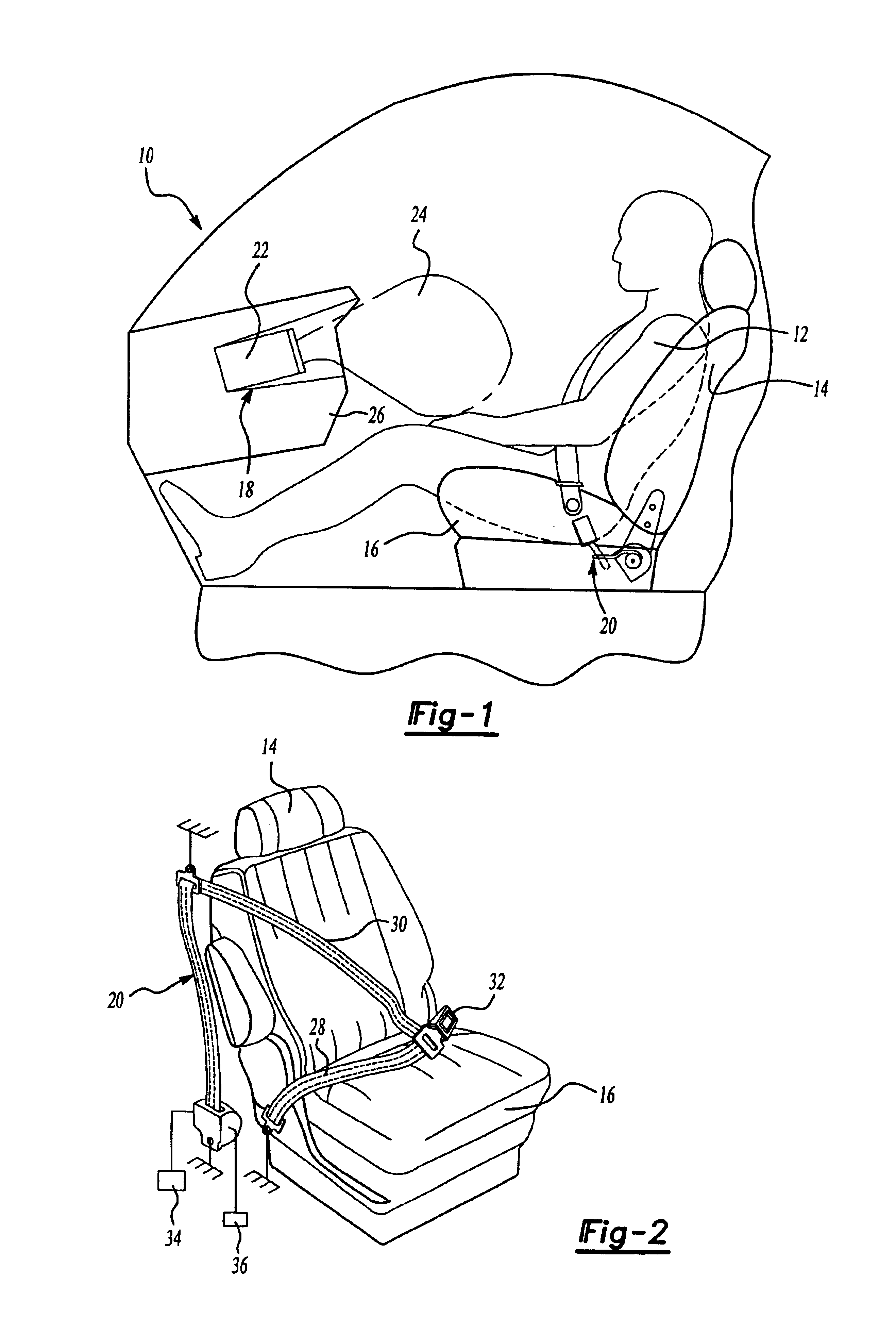
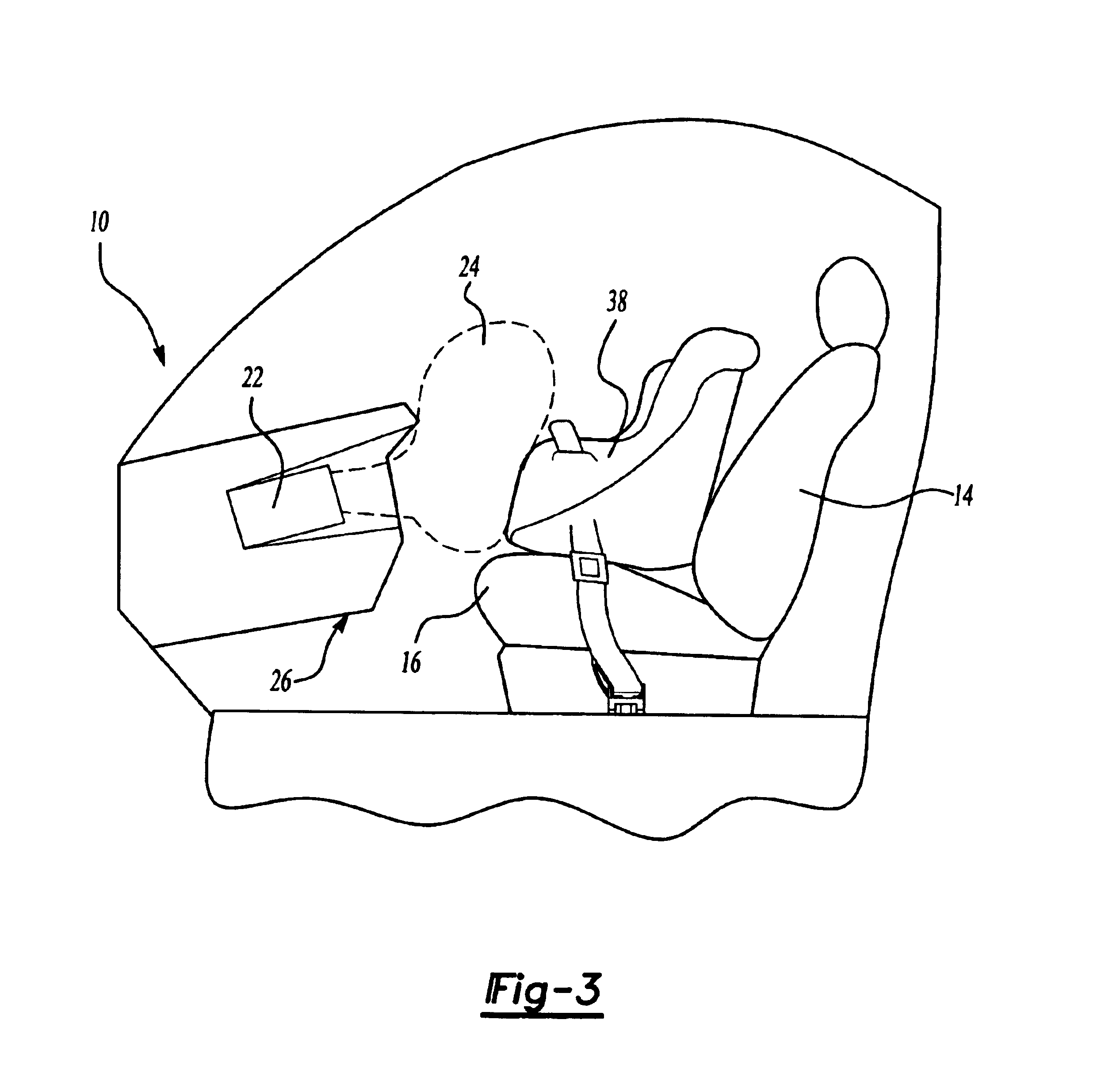
A vehicle is shown generally at 10 in FIG. 1 with an occupant 12 seated in a seat having a seat back 14 supported with respect to a seat bottom 16. The vehicle is equipped with an occupant restraint system that includes an airbag system 18 and a seat belt system 20 that are used to restrain occupants 12 within the vehicle 10 under certain predetermined deceleration requirements. If the vehicle decelerates suddenly, such as when a collision occurs, occupants 12 will tend to continue to move forward due to inertial effects. An airbag controller 22 deploys an airbag 24 under predetermined collision circumstances to decelerate the occupants' impact speed before they contact a vehicle structure, such as a steering wheel or dashboard 26.

The seat belt system 20, shown in FIG. 2, typically includes a lap belt portion 28 and a harness portion 30 that are fastened with a buckle 32 to secure the occupant 12 in the seat. The seat belt system 20 also includes a pretensioner mechanism 34 that pro...


PUM


Abstract

A vehicle occupant restraint system includes an airbag system and a seat belt harness with pretensioner and retractor mechanisms. Multiple sensors are mounted within the vehicle to measure and monitor various occupant and vehicle characteristics, which are entered into a central processing unit (CPU). These sensors include an occupant presence sensor for determining whether there is an occupant present within the airbag deployment area, a child seat sensor for determining whether a child seat is properly installed in the airbag deployment area, and a seat belt usage sensor for determining whether a seat belt is in an engaged position. The occupant presence, child seat, and seat belt usage sensors generate system modifier signals that can disable the airbag system or seat belt mechanisms if certain predetermined conditions are not satisfied. Other sensors include an occupant weight sensor, an occupant proximity sensor for determining occupant position relative to the airbag deployment area, a crash severity sensor, and a pre-crash sensor for providing vehicle speed and orientation characteristics prior to the collision. All of these sensors provide input signals that are received by the CPU. The CPU processes these multiple input signals with a hizzy logic control system to generate multiple output signals for controlling the airbag and seat belt mechanisms. The multiple output signals can include a multi-stage airbag inflation signal, a variable venting signal, a seat belt pretensioner signal, and a seat belt retractor signal.

Description

1. Field of the InventionThis invention relates to a unique method and system for optimizing deployment of an occupant restraint system. The occupant restraint system includes a plurality of sensors that provide multiple input signals to a processing unit that has a fuzzy logic control system for processing the multiple input signals to generate multiple output signals that optimize deployment of the occupant restraint system.2. Related ArtMany vehicles have airbag systems and seat belt mechanisms that are used to restrain occupants within a vehicle under certain deceleration requirements. If the vehicle decelerates suddenly, such as when a collision occurs, occupants will tend to continue to move forward due to inertial effects. An airbag is deployed under these circumstances to decelerate the occupants' impact speed before they contact a vehicle structure, such as a steering wheel or dashboard. Additionally, if the occupant is wearing a seat belt, pretensioner and retractor mechan...

Claims


Application Information

Patent Timeline
Patent Type & Authority Patents(United States)
IPC IPC(8): B60R21/01B60R22/34B60R22/46B60R21/013B60R21/015
CPCB60R21/01516B60R21/01512B60R21/01558B60R21/01556B60R21/013B60R22/34B60R22/46B60R21/01544B60R21/0153
Inventor QUAIL, ALANNA MARIEGARCIA, EMMANUEL
Owner SIEMENS VDO AUTOMOTIVE CORP
Learn More