Vibratory sensor operating as a rate gyro about two axes and as a rate integrating gyro about the third one

a vibration sensor and rate integrating technology, applied in the field of multi-axis sensing devices, can solve the problems of 3.6.degree. heading error for each revolution, and the problem of cumulative error is particularly acu

Inactive Publication Date: 2004-10-19
ATLANTIC INERTIAL SYST
View PDF12 Cites 33 Cited by
  • Summary
  • Abstract
  • Description
  • Claims
  • Application Information

AI Technical Summary

Problems solved by technology

By way of illustration, a 1% scalefactor error will result in a 3.6.degree. heading error for each revolution.
This problem of cumulative error is particularly acute when sensing the motion of a wheel or axle, in which one axis will obviously experience vastly higher rotation rates than the other two axes.

Method used


Image

  • Vibratory sensor operating as a rate gyro about two axes and as a rate integrating gyro about the third one
  • Vibratory sensor operating as a rate gyro about two axes and as a rate integrating gyro about the third one
  • Vibratory sensor operating as a rate gyro about two axes and as a rate integrating gyro about the third one

Examples


Embodiment Construction

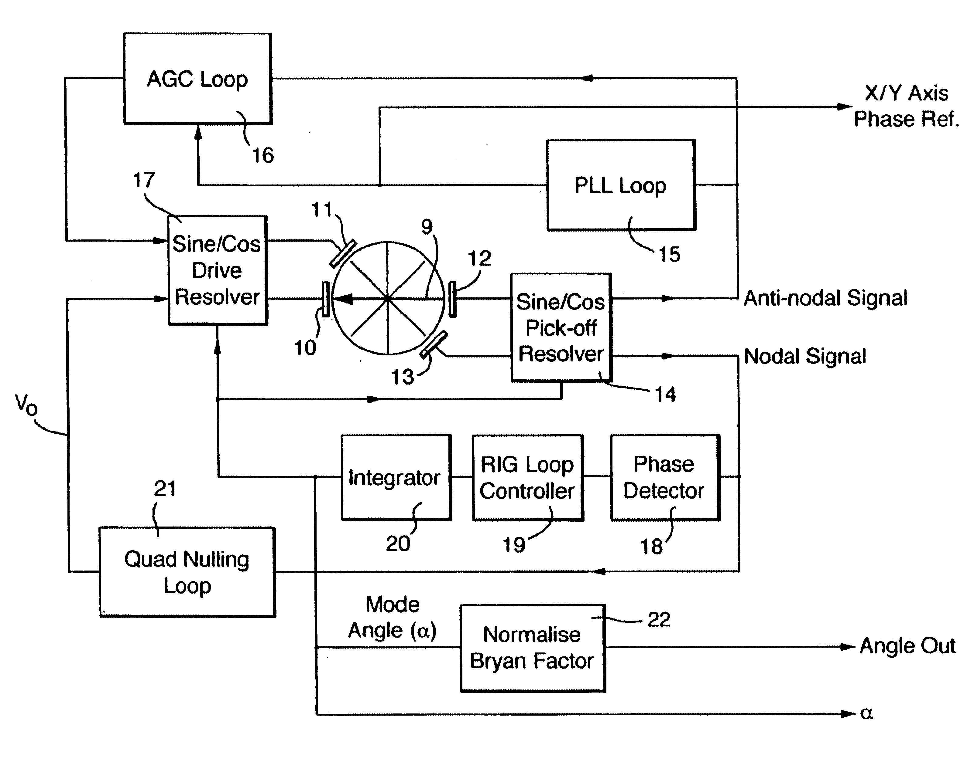
To recap, the present invention contemplates a multi-axis sensing device that operates as a rate gyroscope about two axes, x and y, and as a "whole angle" gyroscope about the third axis, z. With the z-axis gyroscope response implemented in this mode, the carrier mode for the x- and y-axis rate responses is no longer spatially fixed on the ring. A rotation applied around the z-axis will therefore result in the in-plane carrier mode angular position rotating around the ring.

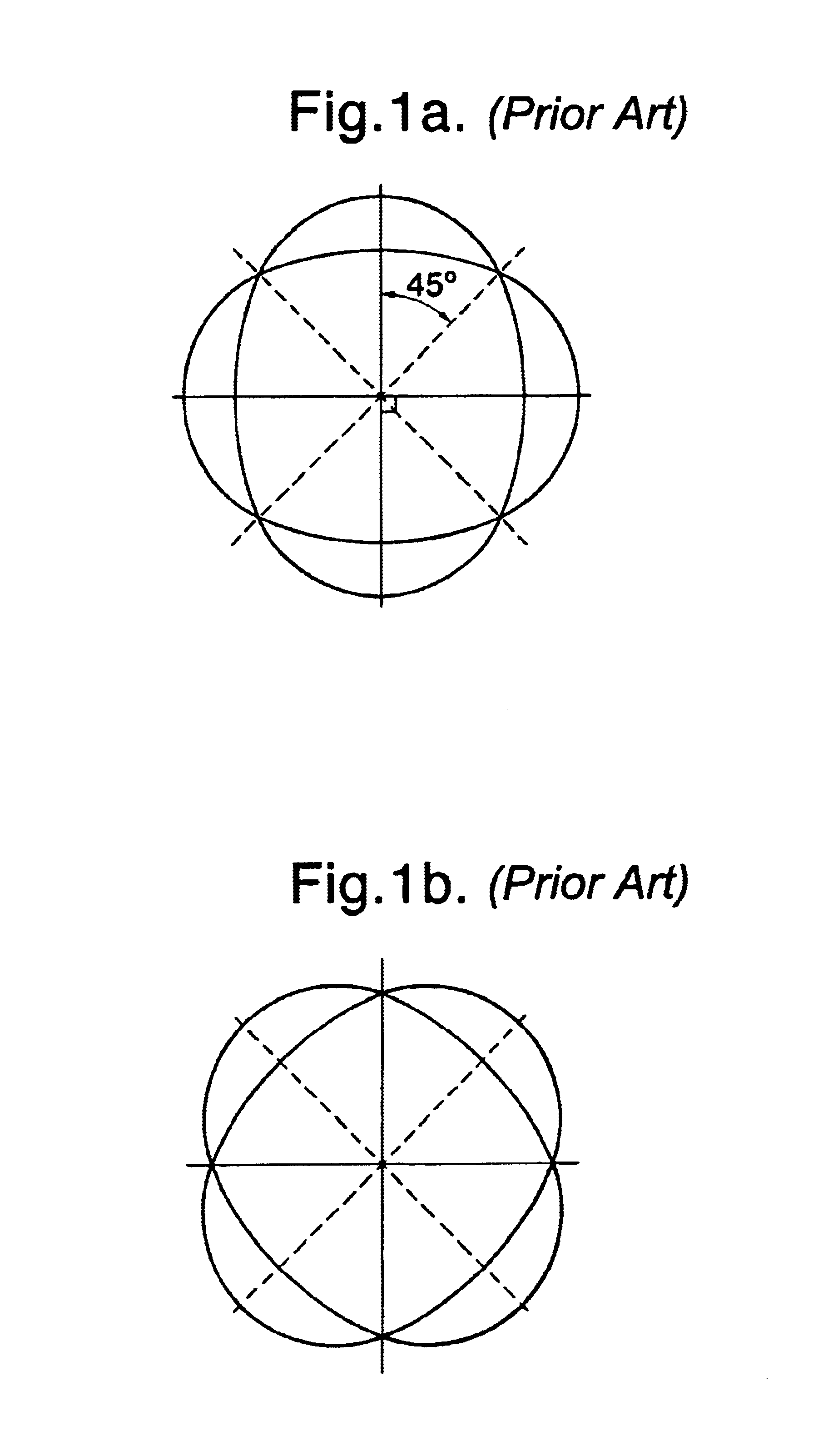
The carrier mode shape may be defined with respect to a fixed angular reference direction. .theta.=0.degree., which is taken to be along a diameter passing through the ring centre. The radial displacement of the ring will have a cos n(.theta.+.alpha.) angular distribution, where .alpha. is the mode angular orientation with respect to the reference direction. The x and y rate response axes may also be defined with respect to the fixed gyroscope body reference axis, the y-axis lying along .theta.=0.degree. and the x-...


PUM


Abstract

A vibrating structure gyroscope comprises a resonant body, a drive transducer for driving resonant motion of the body, a pick-off for producing signals representative of the resonant motion, and a signal processor for extracting z-axis orientation information and x- and y-axis rate information from the signals. The resonant body is planar and the resonant motion takes place in a vibration mode pattern whose orientation angle with respect to the body varies in accordance with z-axis orientation of the body and couples energy into an out-of-plane response mode motion in accordance with rotation of the body about the x- or y-axis. The signal processor resolves the out-of-plane response mode motion with reference to a z-axis orientation signal to extract the x- and y-axis rate information.

Description

1. Field of the InventionThis invention relates to multi-axis sensing devices and more particularly to vibrating structure gyroscopes that employ a resonant element.2. Discussion of Prior ArtVibrating structure gyroscopes have been fabricated using a variety of structures for the resonant element including beams tuning forks, cylinders and rings. Aside from measurement of the rate of rotation about a particular axis, these devices are also capable of operation in "whole angle" or "gyroscope" mode in which the device output gives a direct measure of the angle of rotation about a particular axis, as described in U.S. Pat. No. 5,218,867. This mode of operation is known to give advantages in terms of improved scalefactor performance, particularly in applications where the device is subjected to sustained high rates of rotation.Planar rings have been shown to be particularly versatile, with single-axis rate zero variants being commercially available using both conventionally fabricated a...

Claims


Application Information

Patent Timeline
Patent Type & Authority Patents(United States)
IPC IPC(8): G01C19/56G01C19/5691G01C19/5677
CPCG01C19/5691G01C19/5677
Inventor FELL, CHRISTOPHER PTOWNSEND, KEVIN
Owner ATLANTIC INERTIAL SYST
Why Eureka
Try Eureka