Quick release electrical connector

a technology of electrical connectors and electrical components, which is applied in the direction of coupling device connections, transportation and packaging, vehicle arrangements, etc., can solve the problems of affecting the service life of the electrical connector, and requiring a considerable amount of time for the change-out of the entire electrical apparatus in the aircraft or cabin. to achieve the effect of quick connection and disconn

Inactive Publication Date: 2004-10-26
BE AEROSPACE INCORPORATED
View PDF6 Cites 11 Cited by
  • Summary
  • Abstract
  • Description
  • Claims
  • Application Information

AI Technical Summary

Benefits of technology

to provide an electrical connector that can be quickly connected and disconnected.

Problems solved by technology

For this reason, removal and replacement of the connector element is difficult and time-consuming.
In many instances the connector is in a tight location that is difficult to access, such as under a seat.
A change-out of electrical apparatus in an entire aircraft or cabin thus requires a considerable amount of time.
Dropped and lost screws can become jammed in track fittings or other seating elements and possibly affect seat operation.

Method used


Image

  • Quick release electrical connector
  • Quick release electrical connector
  • Quick release electrical connector

Examples


Embodiment Construction

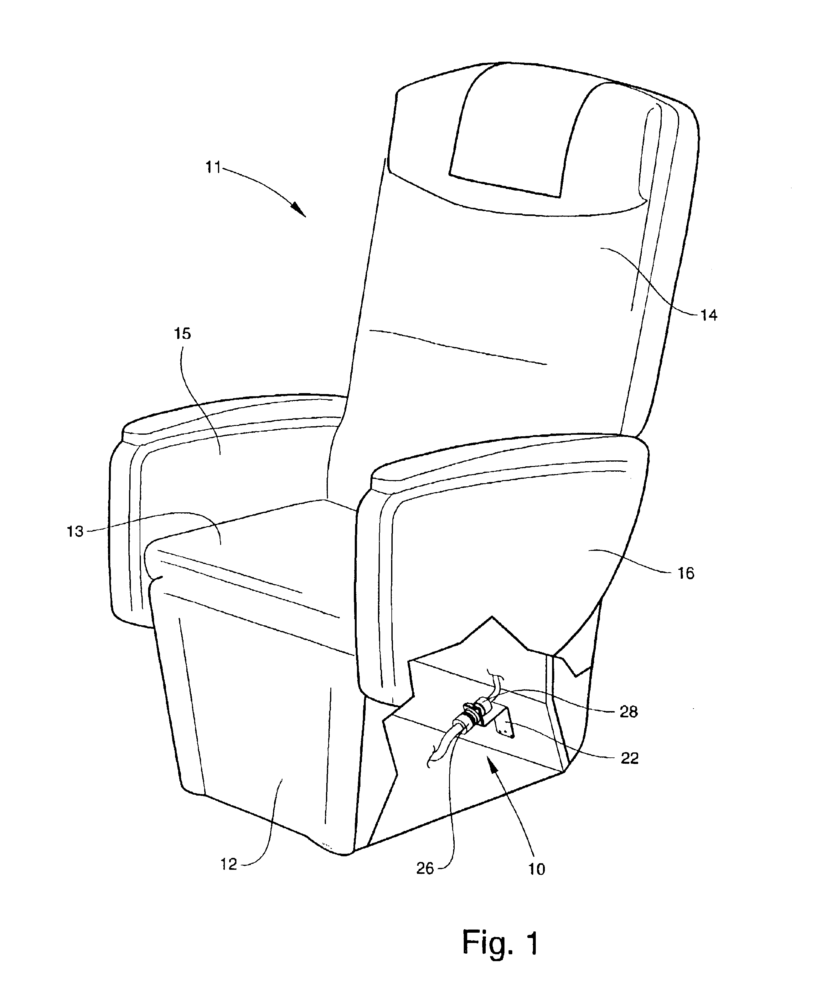
Referring now specifically to the drawings, an electrical connector according to the present invention is illustrated in FIG. 1 and shown generally at reference numeral 10. The electrical connector 10 is shown in a typical application on an aircraft passenger seat 11. The seat 11 includes a base 12, a seat bottom 13, a seat back 14, and a pair of opposed arm rests 15 and 16. In such an application the electrical connector 10 typically connects a source of electricity to an electrical apparatus, for example, an electric motor that controls a seat back, seat bottom or leg rest control to the electrical system of the aircraft.

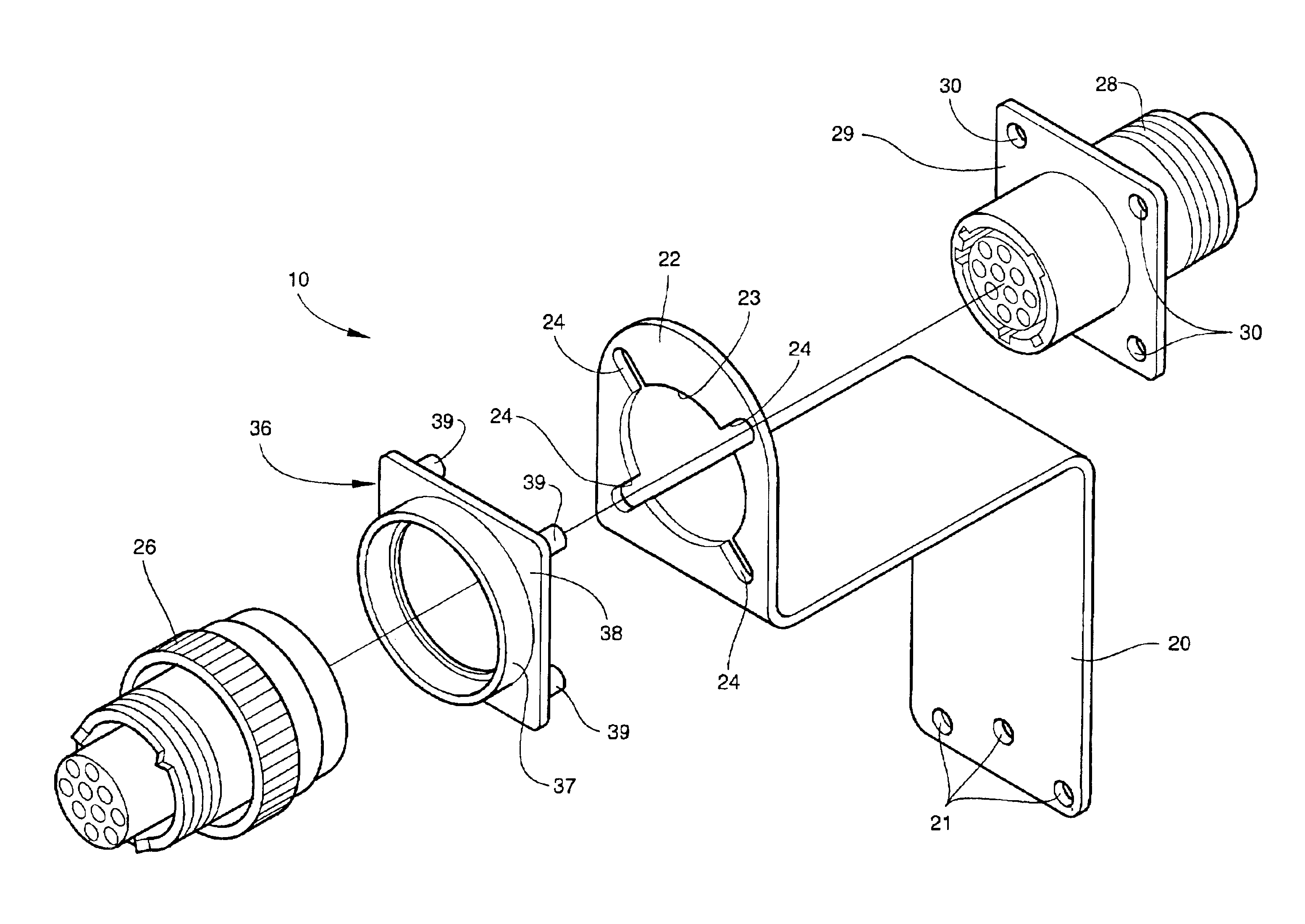
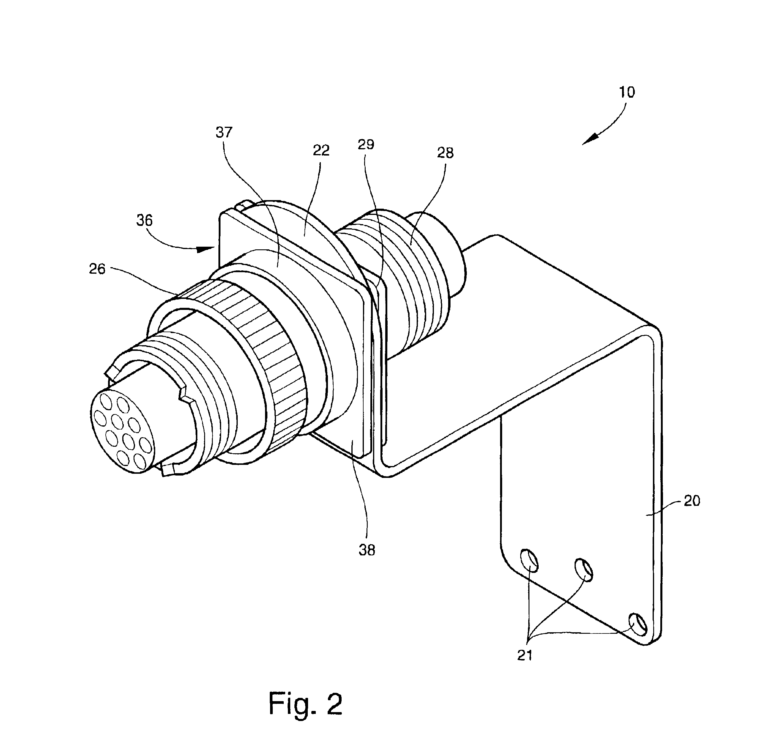
Referring now to FIGS. 2, 3 and 4, the electrical connector 10 comprises a bracket 20 with holes 21 for mounting the bracket 20 to any suitable supporting structure. With particular reference to FIG. 4, the bracket 20 includes a mounting flange 22 in which is formed an annular opening 23 with four radially-extending notches 24 projecting outwardly from the annular...


PUM


Abstract

An electrical connector, including a first electrically-conductive connector element, a second electrically-conductive connector element for being mated with the first connector element for allowing electrical current to flow through the electrical connector from an upstream to a downstream side, and a retainer for receiving and carrying the first connector element. The retainer includes locking anchors for mounting the retainer into complementary locking ports in a mounting bracket whereby the electrical connector is releasably carried on the mounting bracket. The retainer includes a retainer flange on which the locking anchors are mounted. The second connector element includes a connector flange for being mounted on an opposite side of the mounting bracket from the retainer. The connector flange has holes therein for receiving the locking anchors.

Description

TECHNICAL FIELD AND BACKGROUND OF THE INVENTIONThis invention relates to a quick release electrical connector. Connectors of this general type are used in many applications to releasably connect electrical apparatus to an electrical power source. The invention is described in this application with specific reference to use of the connector on an aircraft passenger seat. However, the invention has application in a wide range of uses, and by describing the invention in conjunction with one particular application, no inference is intended that the connector itself is useful only with regard to that one application.Electrical connectors of the general type disclosed in this application include a pair of connection elements that releasably connect together. Most such connectors have bayonet-type locking elements so that the connector elements can be connected or disconnected by twisting one connector relative to the other. One connector element is typically connected to a source of elect...

Claims


Application Information

Patent Timeline
Patent Type & Authority Patents(United States)
IPC IPC(8): H01R13/625H01R13/74B60N2/90
CPCH01R13/625H01R13/746H01R13/633H01R13/60
Inventor PLANT, TOMMY G.SCHATELL, MARC
Owner BE AEROSPACE INCORPORATED
Why Eureka
Try Eureka