Adhesive melter having quick change pump pack assembly and associated methods

a technology of adhesive melters and pump pack assemblies, which is applied in the direction of piston pumps, positive displacement liquid engines, instruments, etc., can solve the problems of increasing the downtime required for repair or replacement of pumps, adding significant time to the downtime required for pump replacement, and affecting the service life of the pump, so as to achieve the effect of quick connection and disconnection

Inactive Publication Date: 2015-01-20
NORDSON CORP
View PDF4 Cites 3 Cited by
  • Summary
  • Abstract
  • Description
  • Claims
  • Application Information

AI Technical Summary

Benefits of technology

[0006]According to one embodiment of the invention, an adhesive melter for use in an adhesive dispensing system includes a melter support frame with a spring-loaded support. The adhesive melter also includes a melter tank and a manifold positioned on the melter support frame, the manifold being configured to receive molten adhesive from the melter tank. A pump pack assembly is also included in the melter, the pump pack assembly having a rigid frame, a pump, a motor, and a drive coupling. The rigid frame includes a base, a pump support member, a rear support member, and at least one fastener connected to the manifold. The pump support member and the rear support member are coupled to the base of the rigid frame. The pump is coupled to the pump support member, and the motor is coupled to the rear support member. The drive coupling operatively connects the pump to the motor. The pump pack assembly is collectively mounted as a unit on the melter support frame by positioning the rigid frame on the spring-loaded support, the pump support member being positioned in fluid-tight engagement with the manifold accommodating the flow of molten adhesive between the pump and manifold. The spring-loaded support assists with resiliently carrying the pump pack assembly at the base as a cantilever load. Therefore, the pump and motor may be quickly connected and disconnected as a unit when maintenance is required without significantly impacting the operational uptime of the adhesive dispensing system.
[0007]The spring-loaded support carries a majority of the cantilever load defined by the pump pack assembly so that the at least one fastener is not damaged by the cantilever load. The fastener may be the only item mechanically securing the pump pack assembly to the melter support frame such that removal of the pump pack assembly can be done by merely loosening the fastener and lifting the rigid frame off of the spring-loaded support. The melter and pump pack assembly may also include a quick change receptacle and a corresponding quick change plug for providing power and control signals to the pump and the motor. A handle may also be provided on the rigid frame to help an operator move the pump pack assembly into and out of engagement with the spring-loaded support.
[0009]In yet another aspect, the pump support member and the rear support member each include a plate extending upwardly from the base. The pump pack assembly may further include a tie rod extending between the pump support member and the rear support member and spaced from the base. The tie rod ensures that the plates of the two support members are aligned in generally parallel relation. The at least one fastener may include a plurality of coupling bolts held captive on the rigid frame and extending between the pump support member and the rear support member. The pump, motor, and drive coupling may therefore be connected and removed from the adhesive melter quickly and easily to save significant downtime that would be experienced otherwise as a result of performing maintenance on these components.

Problems solved by technology

Therefore, the drive coupling that must be used with the pump and motor is expensive and complex to install correctly.
Each of these disassembly and assembly steps add significant time to the downtime required to repair or replace the pump.
On the whole, a routine maintenance of the pump may cause a downtime of as much as an hour.
In certain dispensing fields such as nonwoven article manufacturing where the adhesive dispensing system produces up to $10,000 worth of product per minute, a significant downtime for maintenance can be financially significant.

Method used


Image

  • Adhesive melter having quick change pump pack assembly and associated methods
  • Adhesive melter having quick change pump pack assembly and associated methods
  • Adhesive melter having quick change pump pack assembly and associated methods

Examples


Embodiment Construction

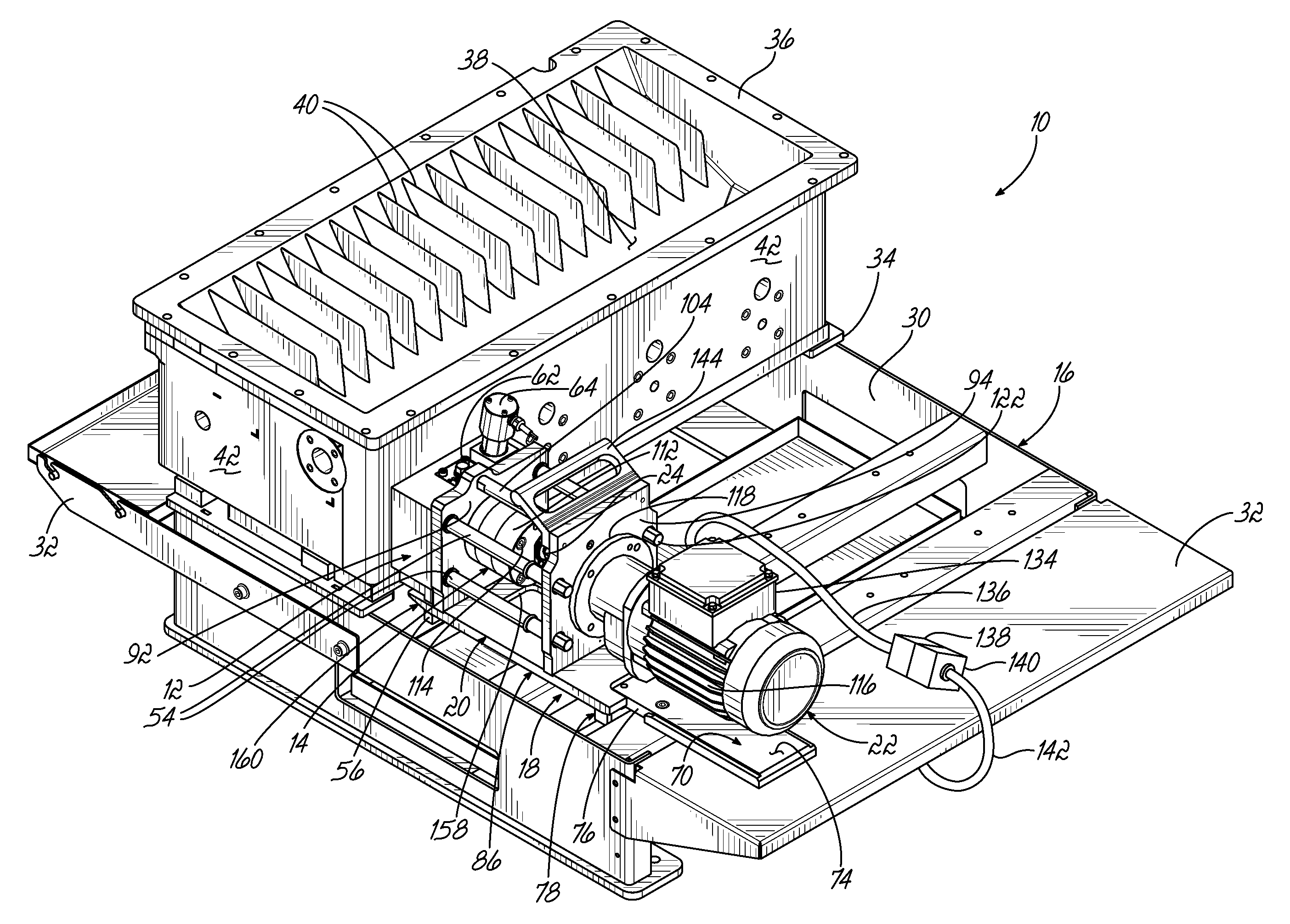
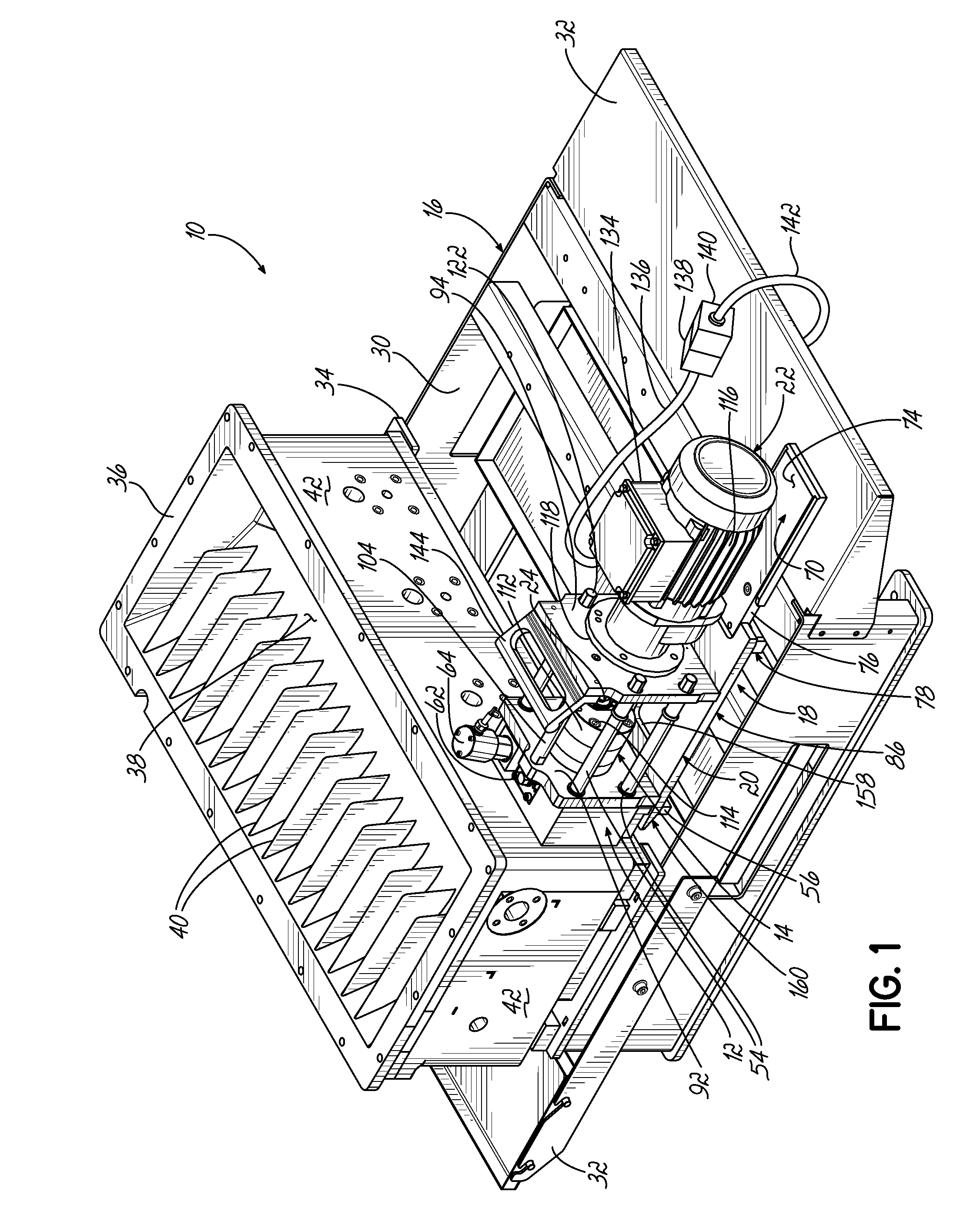
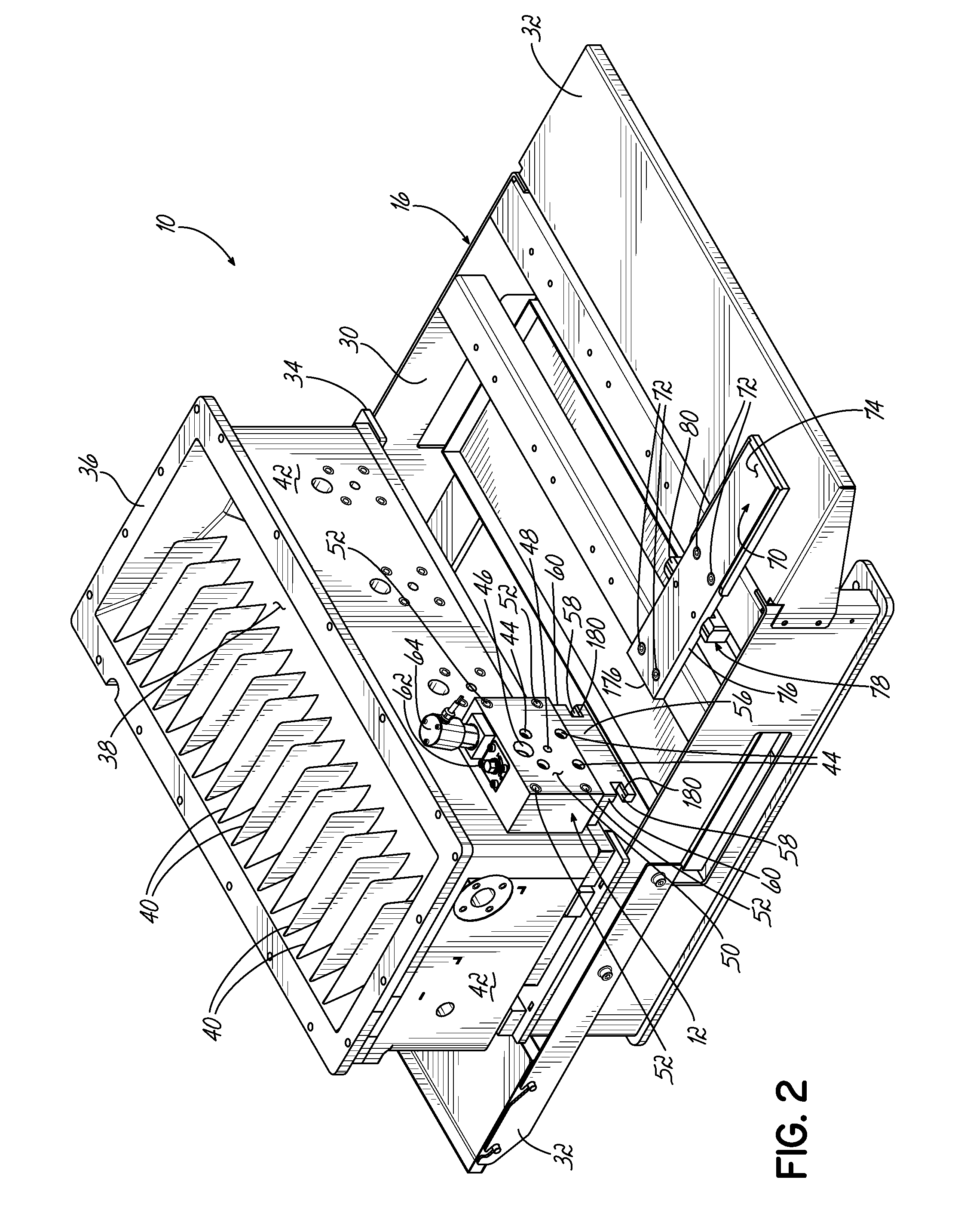
[0023]Referring to FIGS. 1 through 9, an adhesive melter 10 in accordance with an exemplary embodiment of the invention is shown. The adhesive melter 10 is a large tank-type melter 10 configured to melt large amounts of adhesive and supply that adhesive via a manifold 12 and a pump 14 to one or more dispensing devices (not shown) located downstream from the adhesive melter 10. The adhesive melter 10 of the exemplary embodiment includes much of the same structure contained in VersaBlue® melters commercially available from Nordson Corporation of Westlake, Ohio. However, the adhesive melter 10 differs from the known melters in that a quick change pump system and method are used with the adhesive melter 10.

[0024]More particularly, the adhesive melter 10 includes structure on a melter support frame 16 and on the manifold 12 configured to receive a pump pack assembly 18. The pump pack assembly 18 includes a rigid frame 20 carrying the pump 14, a motor 22, and a drive coupling 24 operative...


PUM

PropertyMeasurementUnit
angleaaaaaaaaaa
poweraaaaaaaaaa
heat energyaaaaaaaaaa

Abstract

An adhesive melter includes a melter support frame with a spring-loaded support and a manifold for receiving molten adhesive. The melter also includes a pump pack assembly having a rigid frame carrying a pump for directing flow of molten adhesive through the manifold, a motor, and a drive coupling operatively connecting the pump and motor. The pump pack assembly is collectively mounted as a unit on the melter support frame by positioning the rigid frame on the spring-loaded support, moving the pump into abutment with the manifold, and fastening the pump into fluid-tight engagement with the manifold, the support adjusting in position during fastening to assist with carrying the pump pack assembly as a cantilever load.

Description

FIELD OF THE INVENTION[0001]The present invention generally relates to an adhesive melter used with an adhesive dispensing system and, more particularly, to a pump pack assembly used with the adhesive melter.BACKGROUND[0002]A conventional dispensing system for supplying heated adhesive (i.e., a hot-melt adhesive dispensing system) generally includes a melter configured to receive adhesive in solid or semi-solid form and then heat and / or melt the adhesive, a pump in communication with the melter for driving and controlling the dispensation of the heated adhesive out of the melter, and one or more adhesive dispensing devices (e.g., guns or modules) receiving the heated adhesive from the pump. One or more hoses or manifolds may also be included in the dispensing system to direct the heated adhesive between the melter, pump, and dispensing devices. One particular type of melter used with conventional dispensing systems is a tank melter which includes a relatively large tank for storing ...

Claims


Application Information

Patent Timeline
Patent Type & Authority Patents(United States)
IPC IPC(8): F01C21/00F04B17/06F16L37/00F04B35/06B67D7/62F04C13/00B23P11/00B05C11/10F04C15/00B67D7/82
CPCB23P11/00F16L37/00Y10T29/49238B67D7/82B05C11/10F01C21/007F04B15/02F04B17/06B05C11/1042F04B53/22F04B35/06B67D7/62F04C15/0057Y10T29/49826F04C13/00
Inventor GANZER, CHARLES, P.
Owner NORDSON CORP
Why Eureka
Try Eureka