Hydrodynamic torque converter with at least one axial bearing arrangement for supporting the stator

a technology of axial bearing and stator, which is applied in the direction of interengaging clutches, fluid couplings, gearing, etc., can solve the problems of reducing the distance between the viscous medium and the axial bearing arrangement, and reducing the distance between the viscous medium and the flow passag

Inactive Publication Date: 2004-11-09
ZF FRIEDRICHSHAFEN AG
View PDF13 Cites 19 Cited by
  • Summary
  • Abstract
  • Description
  • Claims
  • Application Information

AI Technical Summary

Benefits of technology

To prevent the bearing side of the support element from undergoing plastic deformation upon the introduction of axial forces, the minimum of one flow passage, which, according to the invention, is provided on the stator side of the support element, i.e., on the side of the support element which faces away from the axial bearing arrangement, with a stiffener in the area over which it extends. By establishing at least a partial connection between the flow bed of the flow passage and the minimum of one boundary wall, this stiffener makes the flow passage more resistant to deformation, but it also has the ability to absorb the axial forces being exerted on the flow bed of the flow passage, which have been absorbed on the bearing side of the support element, and to transmit them onward via the minimum of one boundary wall to the stator side of the support element, so that these axial forces can then be introduced directly into the component (such as the outer freewheel ring) of the stator adjacent to the stator side of the support element. The stiffener is preferably provided on the flow bed at a point where the bed is more susceptible to deformation and where as a result the strength provided by the stiffener is especially effective.
Normally, the flow passage in the support element on the transmission side is used to supply the hydrodynamic circuit with fresh viscous medium, whereas the flow passage in the engine-side support element is used to allow the return of the viscous medium. It is therefore easy to regulate the flow rate in the hydrodynamic circuit via the engine-side flow passage. For this purpose, the engine-side flow passage can have a smaller volume flow rate than the transmission-side flow passage. This volume flow rate can be made even smaller by the stiffener, which projects into the flow passage and thus constricts the flow passage.
Simultaneously, the stiffener can also be used to reduce, if not to eliminate, any residual leakage which may occur from the transmission-side flow passage into the engine-side flow passage; this residual leakage tends to occur primarily in the area where the rolling elements of the freewheel have their radial dimension. The stiffener can reduce the severity of the residual leakage problem by diverting the medium arriving from the transmission-side flow passage back toward the side of its origin, or the stiffener can close off the engine-side flow passage completely or at least almost completely to the viscous medium arriving via the residual leakage connection.

Problems solved by technology

Because relatively high axial forces are exerted on these axial bearing arrangements, it is possible, especially when the support elements are designed with large-volume flow passages on the bearing side, for the bearing disk adjacent to this flow passage to be plastically deformed by the pressure exerted on it by the rolling elements of the compact bearing and thus pressed into the flow passage, which ultimately leads to damage to the axial bearing arrangement and to a narrowing of the flow passage.
To reduce the severity of this problem, it is possible, of course, as done in DE 197 52 187 A1, to design the flow passage with a large component extending in the circumferential direction so that radial contact surfaces for the bearing disk of the compact bearing can be provided at all times on the bearing side of the support element in spite of the flow passages, but this results in an undesirable increase in the distances which the viscous medium must travel within the flow passages.

Method used


Image

  • Hydrodynamic torque converter with at least one axial bearing arrangement for supporting the stator
  • Hydrodynamic torque converter with at least one axial bearing arrangement for supporting the stator
  • Hydrodynamic torque converter with at least one axial bearing arrangement for supporting the stator

Examples


Embodiment Construction

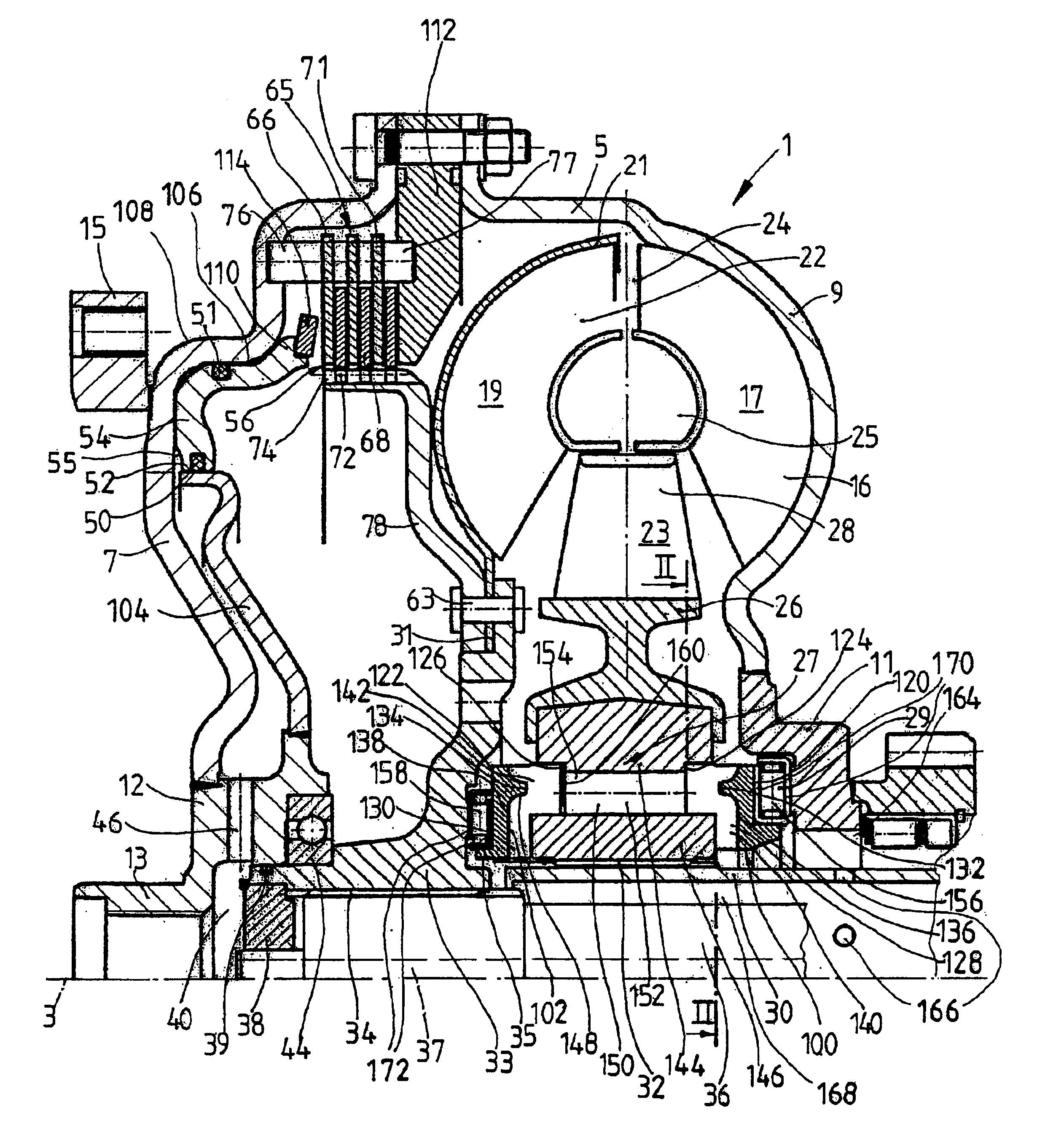
FIG. 1 shows a hydrodynamic torque converter 1, which is able to rotate around an axis of rotation 3. The hydrodynamic torque converter 1 has a converter housing 5, which has a converter cover 7 on the side facing the drive (not shown), such as an internal combustion engine. The cover is permanently connected to a pump wheel shell 9. This shell is connected in its radially inner area to a pump wheel hub 11.

In its radially inner area, the converter cover 7 has a journal hub 12, which carries a bearing journal 13. The journal bearing 13 is mounted on an element of the drive, such as a crankshaft, in a manner known in and of itself (and therefore not shown) in order to center the converter housing 5 on the drive side. In addition, the converter cover 7 also has a mounting 15, which usually serves to attach the converter housing 5 to the drive, preferably by way of a flex plate (not shown). For a drawing of how the bearing journal of a torque converter can be mounted on a crankshaft of ...


PUM


Abstract

A hydrodynamic torque converter is provided with a converter housing to hold at least one pump wheel, one turbine wheel, and one stator to form a hydrodynamic circuit and with at least one axial bearing arrangement for supporting the stator. At least one support element has a bearing side which rests against the axial bearing arrangement, and a stator side which rests against a component of the stator and is designed with at least one flow passage for viscous medium, which forms a connection between at least one flow conduit and the hydrodynamic circuit. The flow passage has a flow bed and, contiguous with that, at least one boundary wall, which leads from the flow bed to the axial level of the corresponding support element side. The bearing side of the support element is essentially flat and the stator side is provided with at least one flow passage, in the extension area of which a stiffener is provided, which produces at least a partial connection between the flow bed of the flow passage and the at least one boundary wall.

Description

1. Field of the InventionThe invention pertains to a hydrodynamic torque converter of the type having a converter housing containing a pump wheel, a turbine wheel and a stator forming a hydrodynamic circuit; at least one axial bearing supporting the stator; and a support element for each axial bearing, the support element having a bearing side in contact with the axial bearing, and a stator side, facing away from the axial bearing, in contact with the stator. At least one flow passage connects at least one flow conduit to said hydrodynamic circuit, the flow passage being defined by a flow bed facing the stator and at least one boundary wall extending from the flow bed to the stator side of the support element.2. Description of the Related ArtA torque converter of this type is known from, for example, DE 197 52 187 A1. The torque converter has a converter housing to hold at least one pump wheel, one turbine wheel, and one stator, where the wheels just mentioned serve to create a hydr...

Claims


Application Information

Patent Timeline
Patent Type & Authority Patents(United States)
IPC IPC(8): F16H41/00F16H41/24F16H45/00F16H45/02F16H41/30
CPCF16H41/24F16H41/30F16H2045/0284F16H2041/246F16H45/02
Inventor JOHANN, HERBERTVESPER, ROMANDAHL, PETRA
Owner ZF FRIEDRICHSHAFEN AG
Why Eureka
Try Eureka