Spring-force clamp connector for an electrical conductor

a technology of clamping connector and electrical conductor, which is applied in the direction of fastening/insulating connecting parts, contact members penetrating/cutting insulation/cable strands, electrical apparatus, etc., can solve the problem of only minimal current conduction value between the inner wall area of the current conduction value between the aperture collar and the clamped electrical conductor is only minimally sufficient. problem, to achieve the effect of solving the problem

Inactive Publication Date: 2004-11-09
WAGO VERW GMBH
View PDF2 Cites 45 Cited by
  • Summary
  • Abstract
  • Description
  • Claims
  • Application Information

AI Technical Summary

Benefits of technology

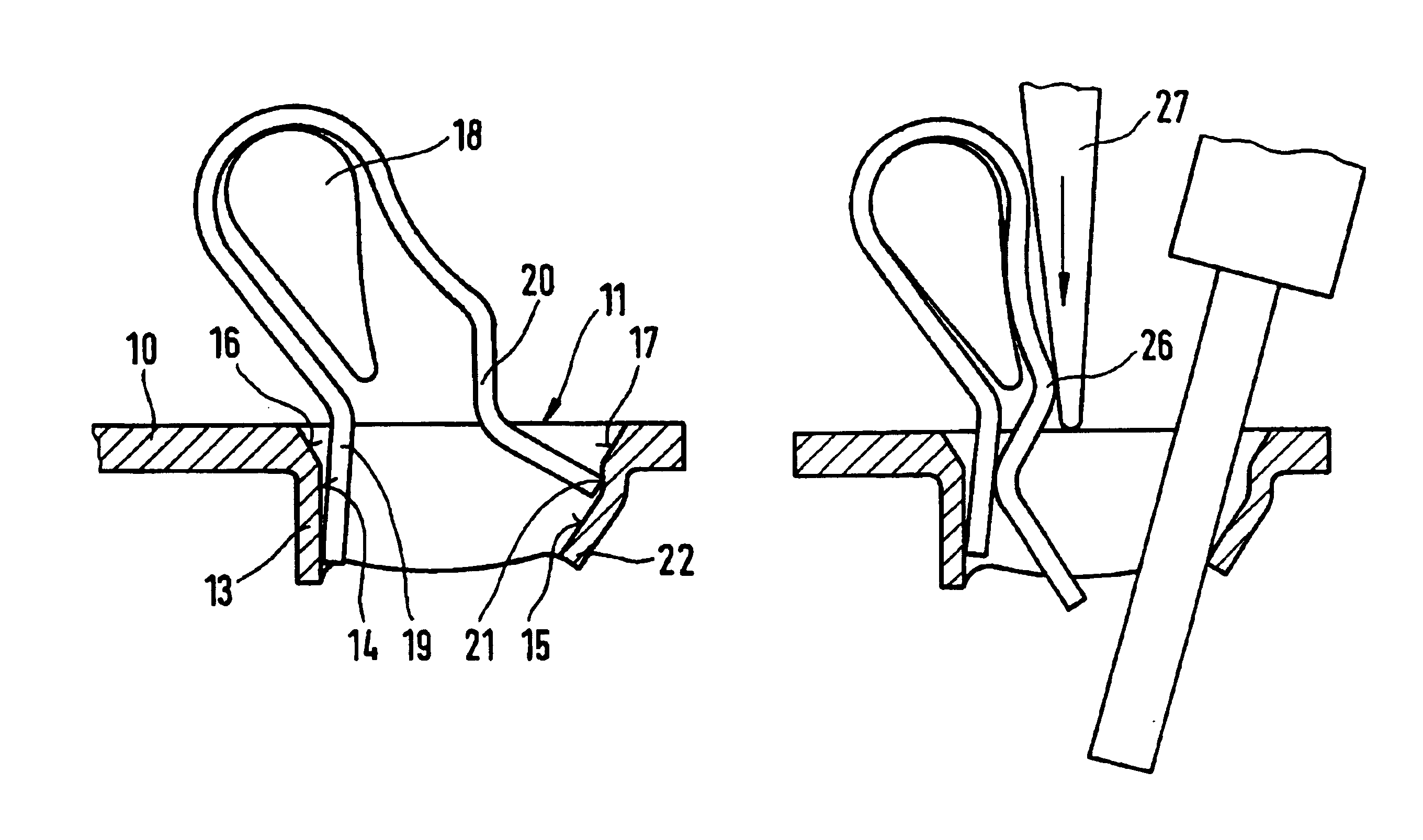
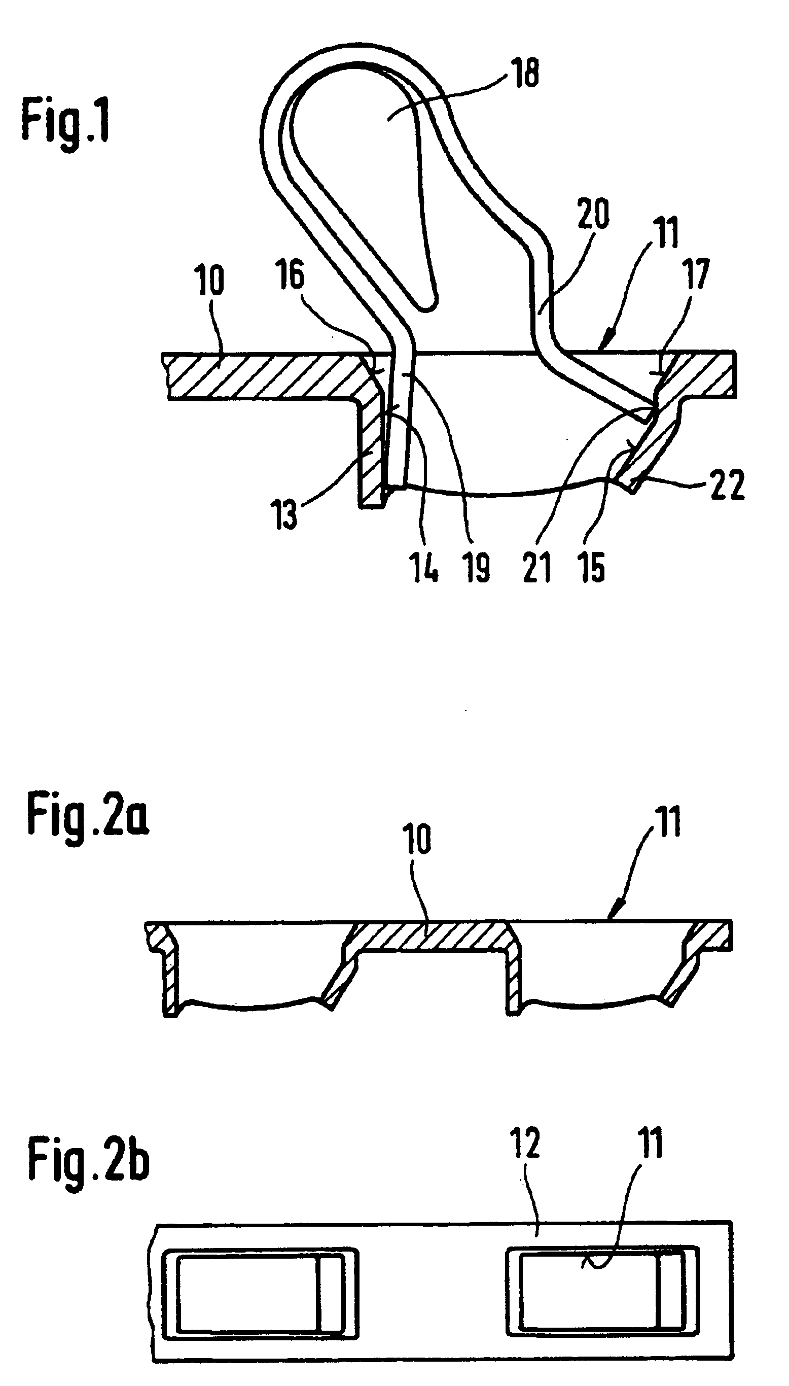
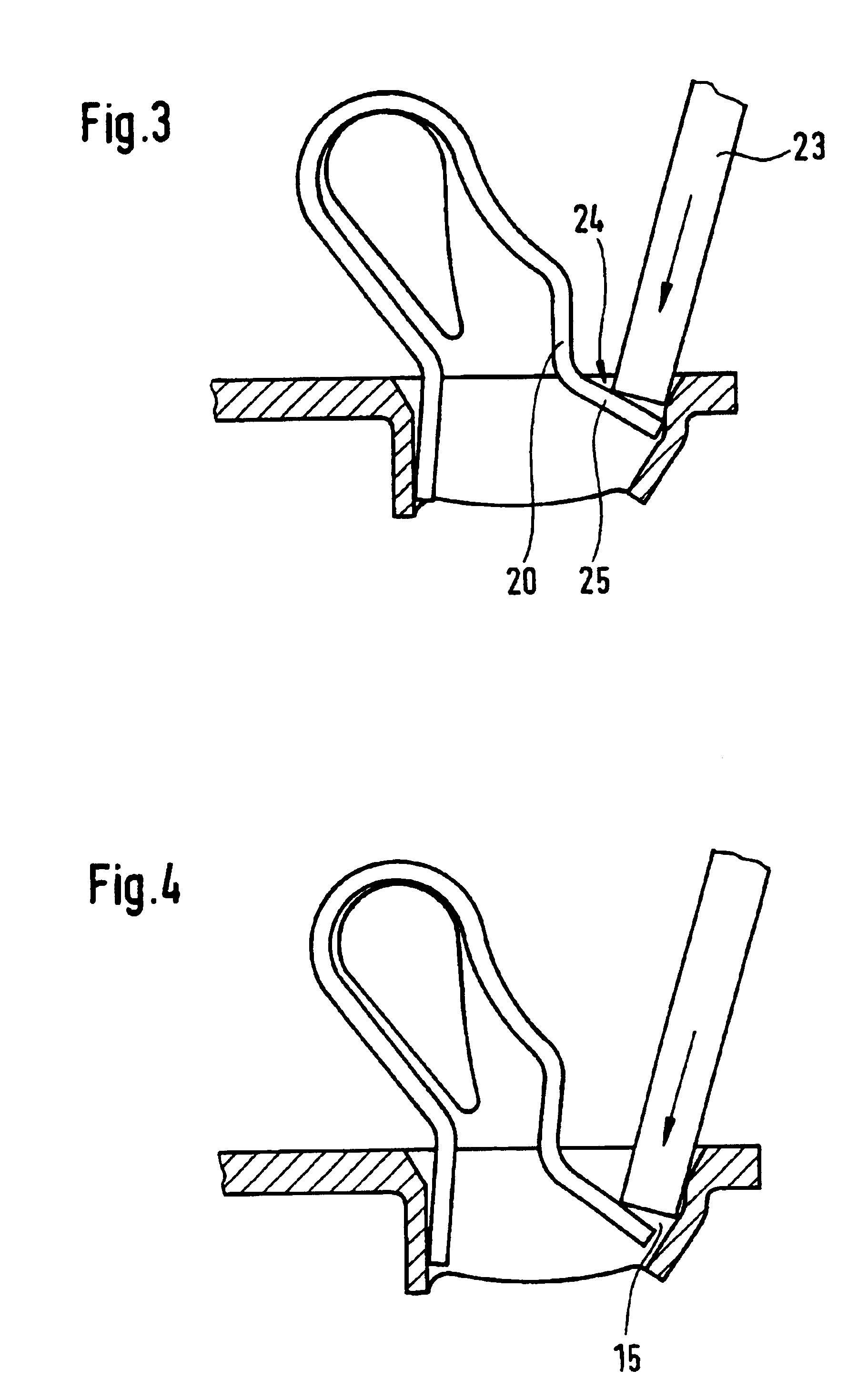
The solution according to the invention is novel for spring-force clamp connectors, which have a material passage with an aperture collar in their conductive core piece, and considerably improves the current transfers and contact safety in the clamping site. This results, first of all, in the advantageous formation of a contact point, which is represented as a crossing point between the electrical conductor and the projecting cross edge at the inner wall area of the aperture collar and which geometrically minimizes the contact surface between the electrical conductor and the aperture collar of the material passage to a smaller, defined contact surface. The improvements also result from a maximal introduction of contact force, which results from the fact that the clamping member of the clamping spring is dimensioned and shaped in such a way that the end-side clamping edge of the end of the clamping member, in the position of clamping of the electrical conductor, acts almost directly on the geometrically minimized contact surface, such that the clamping edge of the end of the clamping member lies roughly opposite the cross edge formed at the inner wall area of the aperture collar. There results from this a high specific pressing of the area of the contact surface, which improves the current transfers and also assures a gas-tight contact.
The positioning of the end of the clamping member of the leaf spring lying approximately opposite the cross edge at the inner wall area of the aperture collar has the further advantage that tilting moments resulting from the clamping force of the leaf spring are not exercized on the clamped electrical conductor.
If, in a preferred manner, the "projecting cross edge" is formed at the inner wall area of the aperture collar by the "introduced lower edge" of the aperture collar of the material passage, then the clamping site for the electrical conductor is maximally displaced deep into the material passage resulting in additional advantages.
Thus, in a preferred embodiment, the region of the inner wall area of the aperture collar, which extends out in front of the clamping site in the direction of plugging in the conductor, can be designed as a relatively large inclined surface and shaped shock-free with smooth transitions (preferably of planar shape). The inclined surface guides the forward end of the electrical conductor in a smooth, sliding manner (i.e., without "hard", jerking transitions) in the insertion process, so that the conductor plug-in forces are reduced and surface coatings which may be present (such as, for example, a tin coating) at the inner wall area of the aperture collar and in the region of the clamping site, are treated gently relative to undesired abrasions.
In another embodiment, a conductor pre-capture pocket for spring-force clamp connectors is disclosed that allows multiwire electrical conductors to be plugged in without problem, without fanning them out and / or otherwise managing to avoid them. In this embodiment, an end-side partial piece of the clamping member of the leaf spring is found within the contour of the material passage in the case of an uncoated and closed clamping site (i.e., it is positioned deep in the material passage) and, in fact, with a surface extent of the partial piece, which is the same size as or larger than the nominal cross section of the conductor to be clamped, such that the annular, closed inner wall area of the aperture collar forms, with the end-side partial piece of the clamping member, a conductor pre-capture pocket that is encased in metal on all sides for the forward end of the electrical conductor to be inserted. In this embodiment, the end-side partial piece of the clamping member of the leaf spring is preferably arranged so that is lies as flat as possible within the contour of the aperture collar. In this manner, a flush arrangement of the front side of the end of the clamping member is made as much as possible against the surface of the electrical conductor. As a result, if forces occur that tend to pull out the conductor, a sharp-edge conductor clamping is avoided. In addition, more sensitive, fine-wire electrical conductors can be clamped without damage.
In another embodiment, a spring-force clamp connector is disclosed which easily releases the clamping site, even when the clamping site is found deep in the material passage. In this embodiment, a central partial piece of the clamping member of the leaf spring lies outside the contour of the material passage and has a front convexity in the direction of the spring clamping force of the clamping member such that a pressing tool placed on this front convexity and substantially perpendicular to the surface of the conductive core piece pushes back the clamping member up to a position in which the clamping site is completely opened. In this manner, the problem encountered in the prior art of when opening the clamping site, being able to push back the clamping member of the leaf spring far enough against its spring force so that the clamping site is optimally, (i.e., completely opened) is solved. This is particularly true if, due to a compact wiring situation, it is necessary that the tool (screwdriver) can only be displaced axially in order to open the clamping site.

Problems solved by technology

In the region of the material passages, such particularly narrow conductive core pieces only have narrow edge pieces running in the direction of the conductive core, and the current-conducting cross sections of these edge pieces are usually insufficient.
This disadvantage is compensated for by the aperture collar of the material passages whose cross sections of the aperture collar are also current-conducting cross sections, so that as a whole, the cross sections of the edge pieces and the cross sections of the aperture collar make available a sufficiently large current-conducting cross section in the direction of the conductive core piece.
However, the known spring-force clamp connectors of this type have the disadvantage that the current conduction values between the inner wall areas of the aperture collar and the clamped electrical conductor are only minimally sufficient.
Practical tests for solving this problem by an increase in clamping forces of the leaf spring have been unsatisfactory, since higher clamping forces unfavorably affect the manually introduced plug-in forces for clamping the electrical conductor.

Method used


Image

  • Spring-force clamp connector for an electrical conductor
  • Spring-force clamp connector for an electrical conductor
  • Spring-force clamp connector for an electrical conductor

Examples


Embodiment Construction

A conductive core piece 10 including a four-cornered material passage 11 is illustrated in FIGS. 1-2b. As best seen in FIGS. 2a and 2b, material passages 11 of random number may preferably be positioned in a row closely adjacent to one another. The shape of a narrow strip of material, which has edge pieces 12 with a small width in the region of the material passages, can be selected for the conductive core piece.

In the present embodiment, the material passage 11 preferably includes an annular, closed aperture collar 13 having inner wall areas 14 and 15. The collar 13 is preferably condituous with the upper side of the conductive core piece. The transitions from the upper side of the conductive core piece on the inner wall areas of the aperture collar can be shaped as round or oblique lead-in places 16 and 17, respectively.

In the material passage 11, a substantially U-shaped bent leaf spring can be inserted. The leaf spring sits with its rear spring arc on a plastic projection piece ...


PUM


Abstract

The invention concerns a spring-force clamp connector for connecting an electrical conductor, which has a conductive core piece with a four-cornered material passage according to this design, in which the end of the clamping member of a leaf spring penetrates such that the end of the clamping member forms a clamping site for the electrical conductor together with an inner wall area of the aperture collar of the material passage. It is proposed to use for the inner wall area of the aperture collar of the material passage a new shaping with a cross edge / edge and to arrange the clamping site for the electrical conductor deep in the material passage, whereby at the same time a metal-encased conductor pre-capture pocket is formed.

Description

The invention relates generally to an electrical spring-force clamp connector and, more specifically, to a spring-force clamp connector with a conductive core piece and a leaf spring for connecting an electrical conductor.BACKGROUND OF RELATED ARTA basic design feature of conventional spring-force clamp connectors is a four-cornered material passage through the conductive core piece, which is made of a flat material. This passage serves as the opening for through-passage of the conductor and has an aperture collar extending in the direction of the conductor through-passage, so that a clamping site for an electrical conductor is formed between the inner wall surface of the aperture collar and one end of a leaf spring extending through the material passage (see, for example, DE 2,825,291 C2).Such conductive core pieces can be provided with one or even several material passages. These passages are preferably arranged in a row in order to obtain as narrow a structural shape of the condu...

Claims


Application Information

Patent Timeline
Patent Type & Authority Patents(United States)
IPC IPC(8): H01R4/48H01R9/24
CPCH01R4/4827H01R4/4818H01R4/48275H01R4/48185H01R4/48
Inventor KOLLMANN, HANS-JOSEF
Owner WAGO VERW GMBH
Why Eureka
Try Eureka