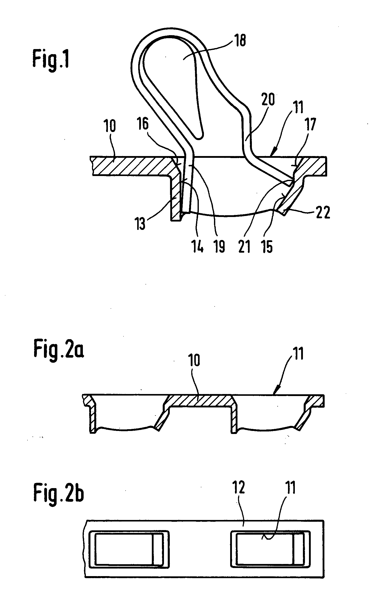
[0009] The solution according to the invention is novel for spring-force clamp connectors, which have a material passage with an aperture collar in their conductive core piece, and considerably improves the current transfers and contact safety in the clamping site. This results, first of all, in the advantageous formation of a contact point, which is represented as a crossing point between the electrical conductor and the projecting cross edge at the inner wall area of the aperture collar and which geometrically minimizes the contact surface between the electrical conductor and the aperture collar of the material passage to a smaller, defined contact surface. The improvements also result from a maximal introduction of
contact force, which results from the fact that the clamping member of the clamping spring is dimensioned and shaped in such a way that the end-side clamping edge of the end of the clamping member, in the position of clamping of the electrical conductor, acts almost directly on the geometrically minimized contact surface, such that the clamping edge of the end of the clamping member lies roughly opposite the cross edge formed at the inner wall area of the aperture collar. There results from this a high specific pressing of the area of the contact surface, which improves the current transfers and also assures a gas-tight contact.
[0010] The positioning of the end of the clamping member of the leaf spring
lying approximately opposite the cross edge at the inner wall area of the aperture collar has the further
advantage that tilting moments resulting from the clamping force of the leaf spring are not exercized on the clamped electrical conductor.
[0011] If, in a preferred manner, the "projecting cross edge" is formed at the inner wall area of the aperture collar by the "introduced lower edge" of the aperture collar of the material passage, then the clamping site for the electrical conductor is maximally displaced deep into the material passage resulting in additional advantages.
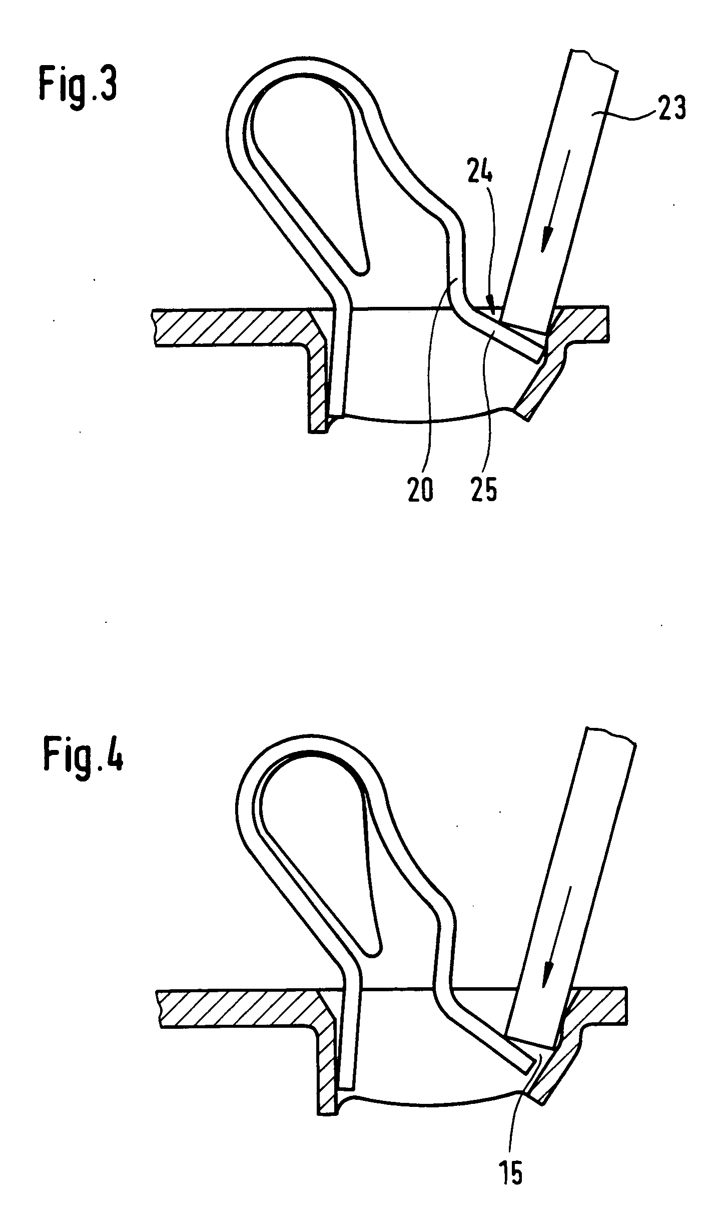
[0012] Thus, in a preferred embodiment, the region of the inner wall area of the aperture collar, which extends out in front of the clamping site in the direction of plugging in the conductor, can be designed as a relatively large inclined surface and shaped shock-free with smooth transitions (preferably of planar shape). The inclined surface guides the forward end of the electrical conductor in a smooth, sliding manner (i.e., without "hard", jerking transitions) in the
insertion process, so that the conductor plug-in forces are reduced and surface coatings which may be present (such as, for example, a
tin coating) at the inner wall area of the aperture collar and in the region of the clamping site, are treated gently relative to undesired abrasions.
[0013] In another embodiment, a conductor pre-capture pocket for spring-force clamp connectors is disclosed that allows multiwire electrical conductors to be plugged in without problem, without fanning them out and / or otherwise managing to avoid them. In this embodiment, an end-side partial piece of the clamping member of the leaf spring is found within the contour of the material passage in the case of an uncoated and closed clamping site (i.e., it is positioned deep in the material passage) and, in fact, with a surface extent of the partial piece, which is the same size as or larger than the nominal cross section of the conductor to be clamped, such that the annular, closed inner wall area of the aperture collar forms, with the end-side partial piece of the clamping member, a conductor pre-capture pocket that is encased in
metal on all sides for the forward end of the electrical conductor to be inserted. In this embodiment, the end-side partial piece of the clamping member of the leaf spring is preferably arranged so that is lies as flat as possible within the contour of the aperture collar. In this manner, a flush arrangement of the front side of the end of the clamping member is made as much as possible against the surface of the electrical conductor. As a result, if forces occur that tend to pull out the conductor, a sharp-edge conductor clamping is avoided. In addition, more sensitive, fine-wire electrical conductors can be clamped without damage.
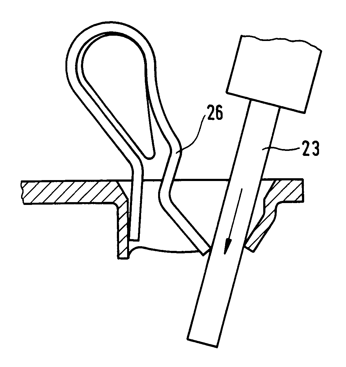
[0015] In another embodiment, a spring-force clamp connector is disclosed which easily releases the clamping site, even when the clamping site is found deep in the material passage. In this embodiment, a central partial piece of the clamping member of the leaf spring lies outside the contour of the material passage and has a front convexity in the direction of the spring clamping force of the clamping member such that a pressing tool placed on this front convexity and substantially perpendicular to the surface of the conductive core piece pushes back the clamping member up to a position in which the clamping site is completely opened. In this manner, the problem encountered in the prior art of when opening the clamping site, being able to push back the clamping member of the leaf spring far enough against its
spring force so that the clamping site is optimally, (i.e., completely opened) is solved. This is particularly true if, due to a compact wiring situation, it is necessary that the tool (screwdriver) can only be displaced axially in order to open the clamping site.

