Wrench extension with a socket-coupling system

Inactive Publication Date: 2004-11-30
HU BOBBY
View PDF13 Cites 37 Cited by
  • Summary
  • Abstract
  • Description
  • Claims
  • Application Information

AI Technical Summary

Benefits of technology

An object of the present invention is to provide a wrench extension with a socket-coupling system allowing quick attachment/detachment o

Problems solved by technology

Nevertheless, when the socket coupled to the end of the extension shaft is subject to an external force and thus moves in a direction away from the extension shaft, the ball is forced to move downward and causes inward movement of the transmission member.
This is because no retaining means is provided for retai

Method used


Image

  • Wrench extension with a socket-coupling system
  • Wrench extension with a socket-coupling system
  • Wrench extension with a socket-coupling system

Examples


Embodiment Construction

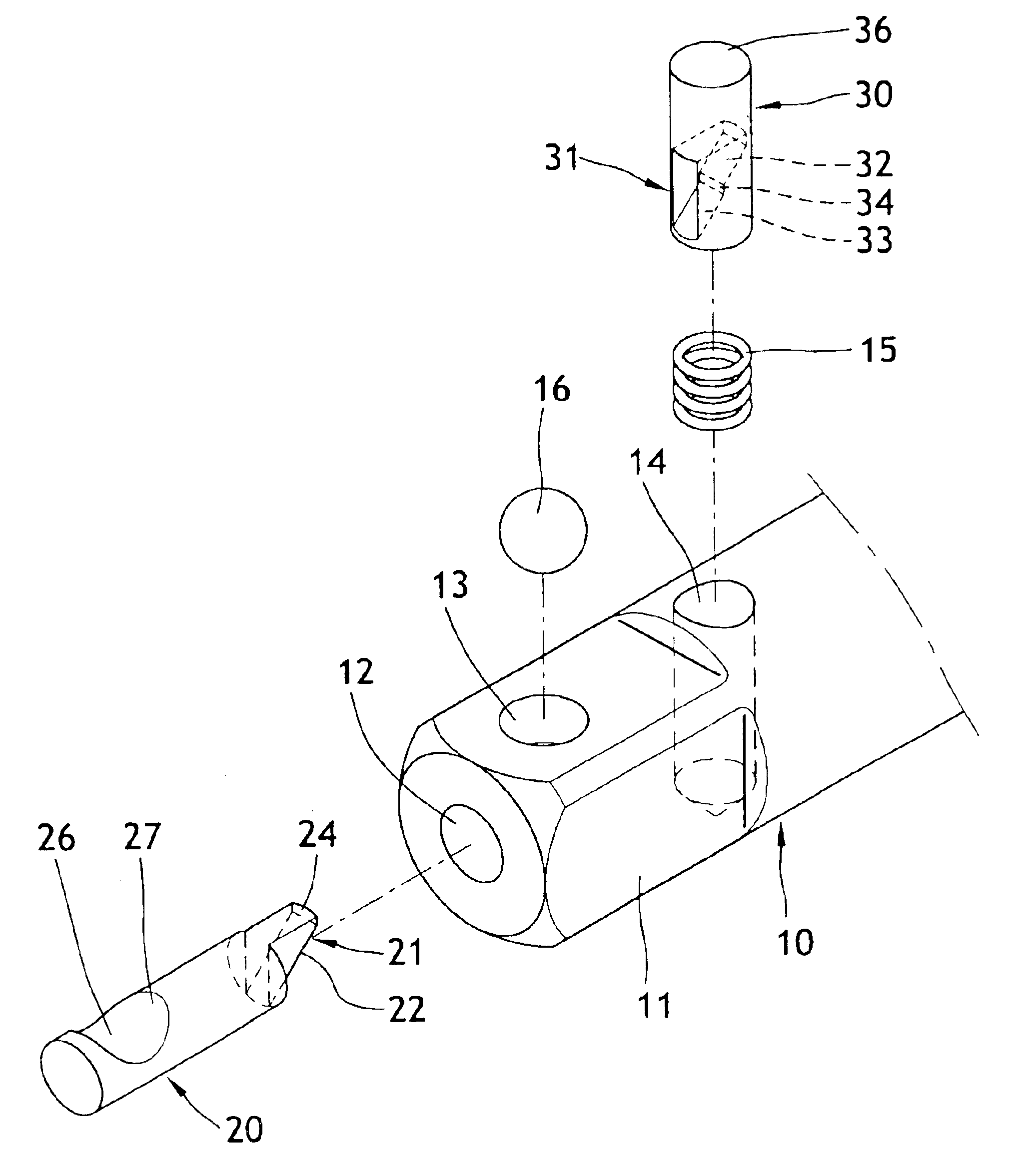
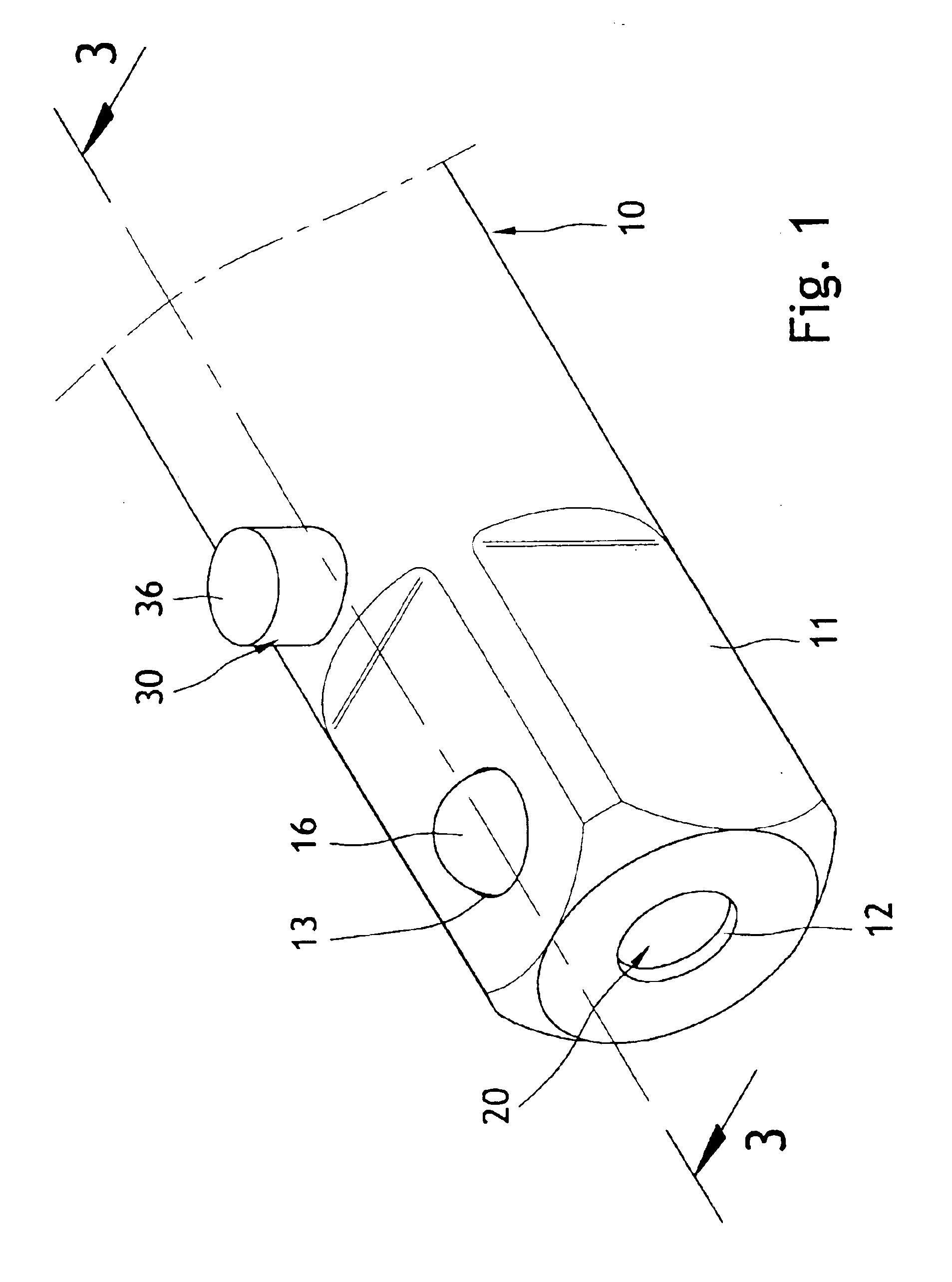
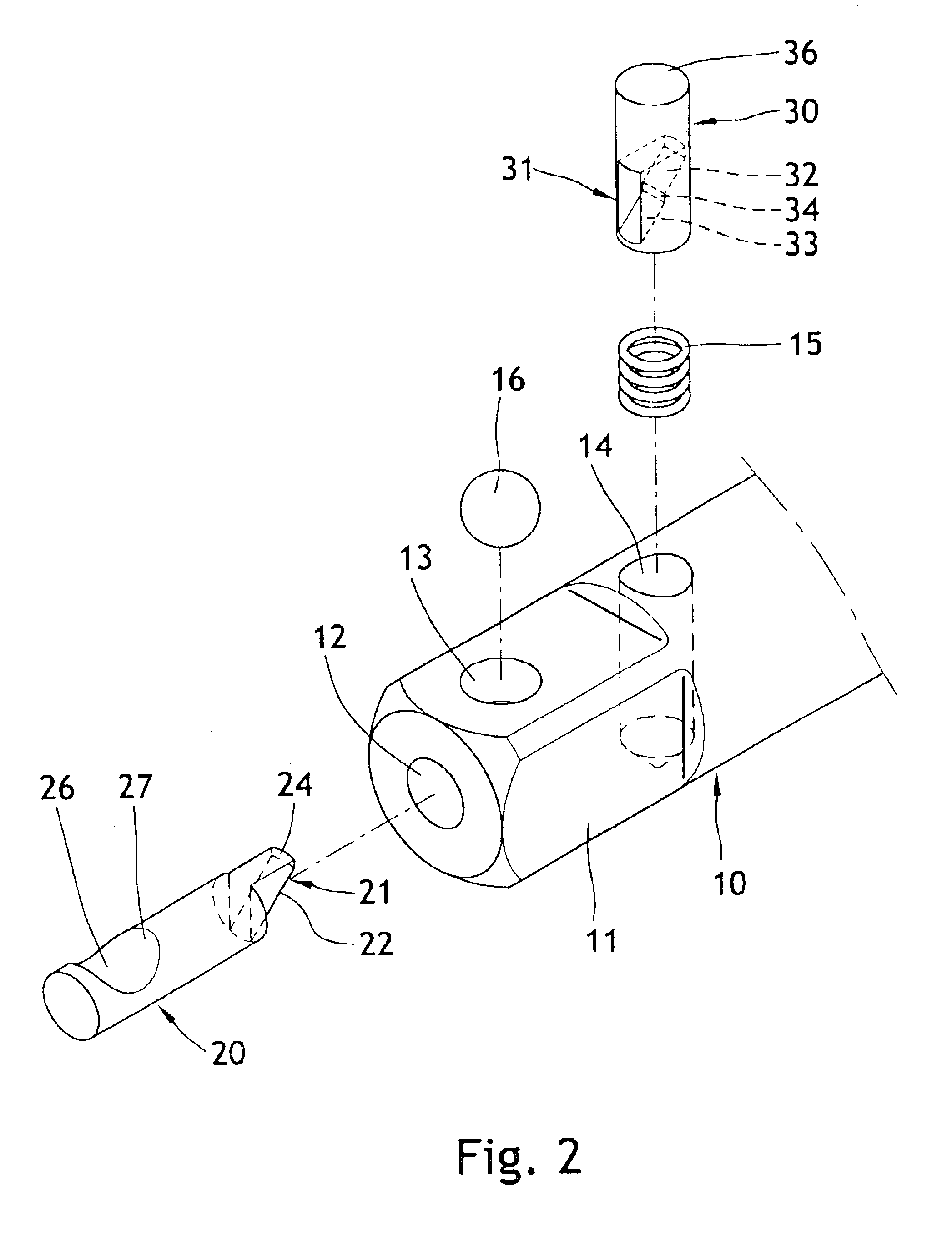
Referring to FIGS. 1 through 3, a first embodiment of a wrench extension in accordance with the present invention generally comprises a wrench extension shaft 10 having an end 11 that is generally square for releasably engaging with a socket 40 (FIG. 4) having a cavity 42 with a detent 41. The end 11 of the wrench extension shaft 10 includes an axial passageway 12 extending along a longitudinal direction of the wrench extension shaft 10. Also defined in the end 11 of the wrench extension shaft 10 is a first transverse passageway 13 extending in a direction transverse to the longitudinal direction of the wrench extension shaft 10 and having an inner end communicated with the axial passageway 12 and an outer end communicated with outside. A second transverse passageway 14 is defined in an outer periphery of the wrench extension shaft 10 at a location adjacent to the end 11 of the wrench extension shaft 10. The second transverse passageway 14 extends in a direction transverse to the lo...


PUM


Abstract

A wrench extension with a socket-coupling system includes a socket extension shaft, a transmission member mounted in an axial passageway in an end of the wrench extension shaft, a ball mounted in a first transverse passageway in the end of the wrench extension shaft, and a push member mounted in a second transverse passageway in the wrench extension shaft. The transmission member includes a sliding portion that is in sliding contact with a sliding portion of the push member for urging the ball into a detent of a cavity of a socket coupled to the end of the wrench extension shaft. When the socket is subject to an axial force away from the wrench extension shaft, the transmission member is stopped by the push member to thereby prevent undesired decoupling of the socket.

Description

BACKGROUND OF THE INVENTION1. Field of the InventionThe present invention relates to a wrench extension with a socket-coupling system allowing quick attachment / detachment of a socket to / from an end of the wrench extension shaft.2. Description of the Related ArtU.S. Pat. No. 5,531,140 discloses a coupling mechanism of socket wrench extension including an extension shaft (body). A first transverse passageway (opening) is defined in an end of the extension shaft and extends radially. A second transverse passageway (orifice) is defined in the extension shaft and adjacent to the end of the extension shaft. An axial passageway (axial bore) extends longitudinally from an end face of the end of the extension shaft and communicates with the first transverse passageway and the second transverse passageway. A transmission member (rod) is mounted in the axial passageway, and a spring is mounted in an inner end of the axial passageway with two ends of the spring respectively attached to an end w...

Claims


Application Information

Patent Timeline
IPC IPC(8): B25B23/00
CPCB25B23/0035Y10T403/592Y10T403/599
Inventor HU, BOBBY
Owner HU BOBBY
Why Eureka
Try Eureka