Another advantage of the present invention is seen in a multi-cavity system in which the nozzles are injecting into cavities which form different sized parts that require different fill rates and packing profiles. In this case, different pressure profiles can be programmed for each respective controller of each respective cavity. Still another advantage is when the size of the cavity is constantly changing, i.e., when making different size parts by changing a mold insert in which the part is formed. Rather than change the hardware (e.g., the nozzle) involved in order to change the fill rate and packing profile for the new part, a new program is chosen by the user corresponding to the new part to be formed.
is seen in a multi-cavity system in which the nozzles are injecting into cavities which form different sized parts that require different fill rates and packing profiles. In this case, different pressure profiles can be programmed for each respective controller of each respective cavity. Still another advantage is when the size of the cavity is constantly changing, i.e., when making different size parts by changing a mold insert in which the part is formed. Rather than change the hardware (e.g., the nozzle) involved in order to change the fill rate and packing profile for the new part, a new program is chosen by the user corresponding to the new part to be formed.
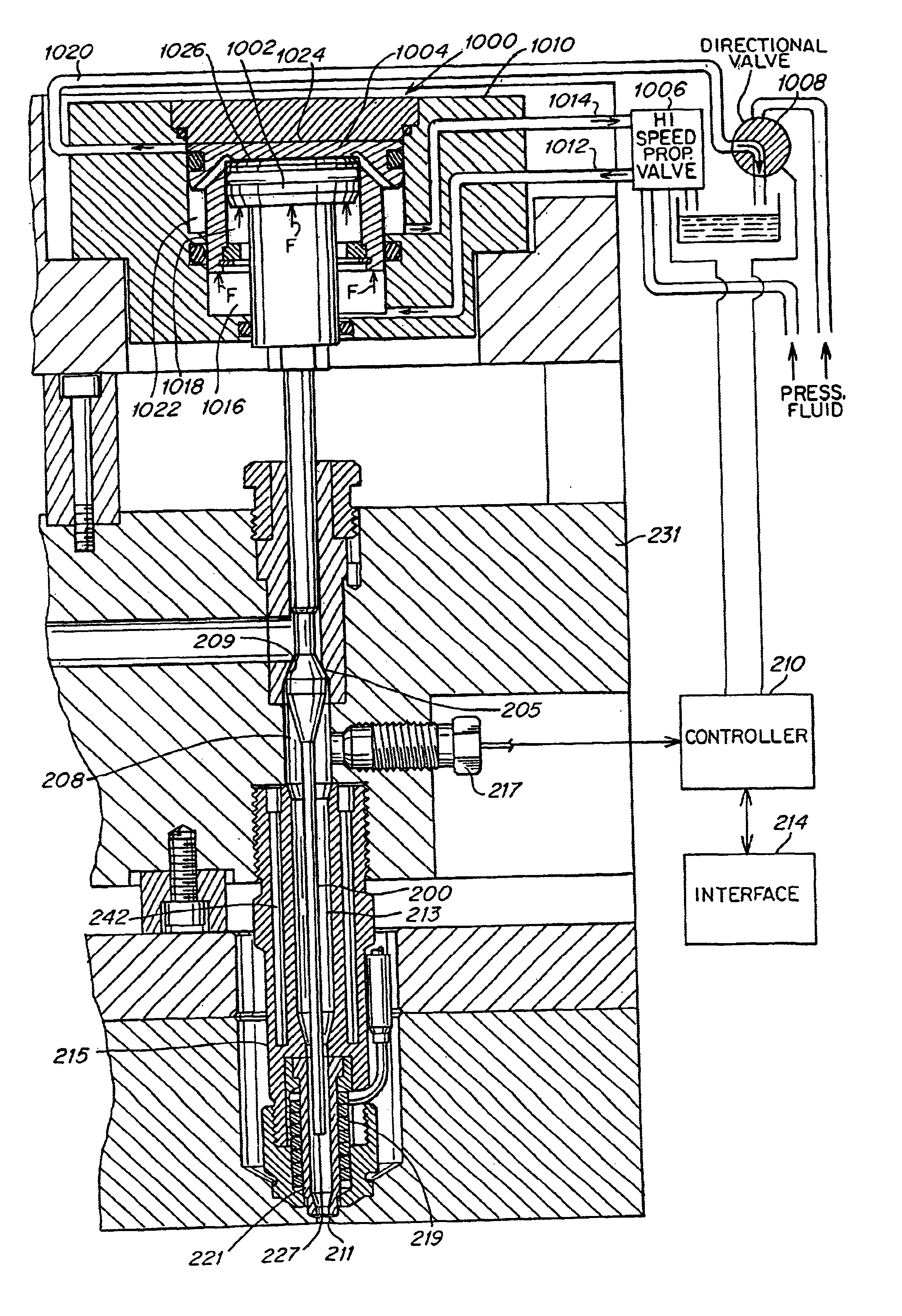
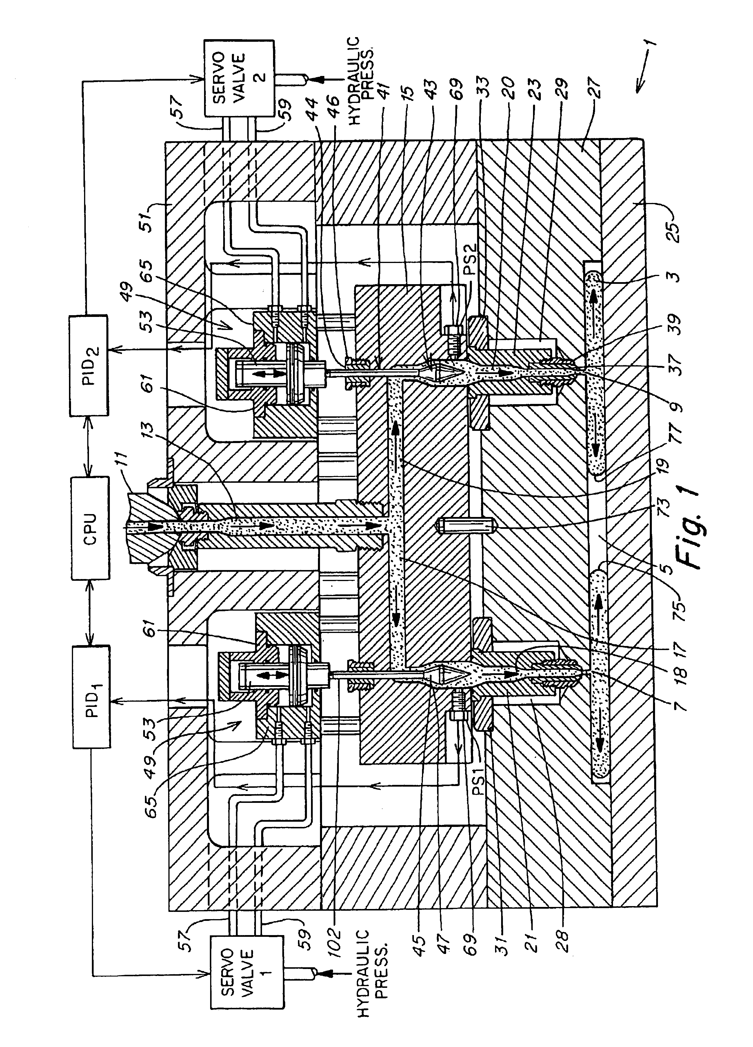
The embodiment of FIGS. 1 and 2 has the advantage of controlling the rate of melt flow away from the gate inside manifold 15 rather than at the gates 7 and 9. Controlling the melt flow away from the gate enables the pressure transducer to be located away from the gate (in FIGS. 1-5). In this way, the pressure transducer does not have to be placed inside the mold cavity, and is not susceptible to pressure spikes which can occur when the pressure transducer is located in the mold cavity or near the gate. Pressure spikes in the mold cavity result from the valve pin being closed at the gate. This pressure spike could cause an unintended response from the control system, for example, an opening of the valve pin to reduce the pressure--when the valve pin should be closed.
Avoidance of the effects of a pressure spike resulting from closing the gate to the mold makes the control system behave more accurately and predictably. Controlling flow away from the gate enables accurate control using only a single sensed condition (e.g., pressure) as a variable. The '582 patent disclosed the use of two sensed conditions (valve position and pressure) to compensate for an unintended response from the pressure spike. Sensing two conditions resulted in a more complex control algorithm (which used two variables) and more complicated hardware (pressure and position sensors).
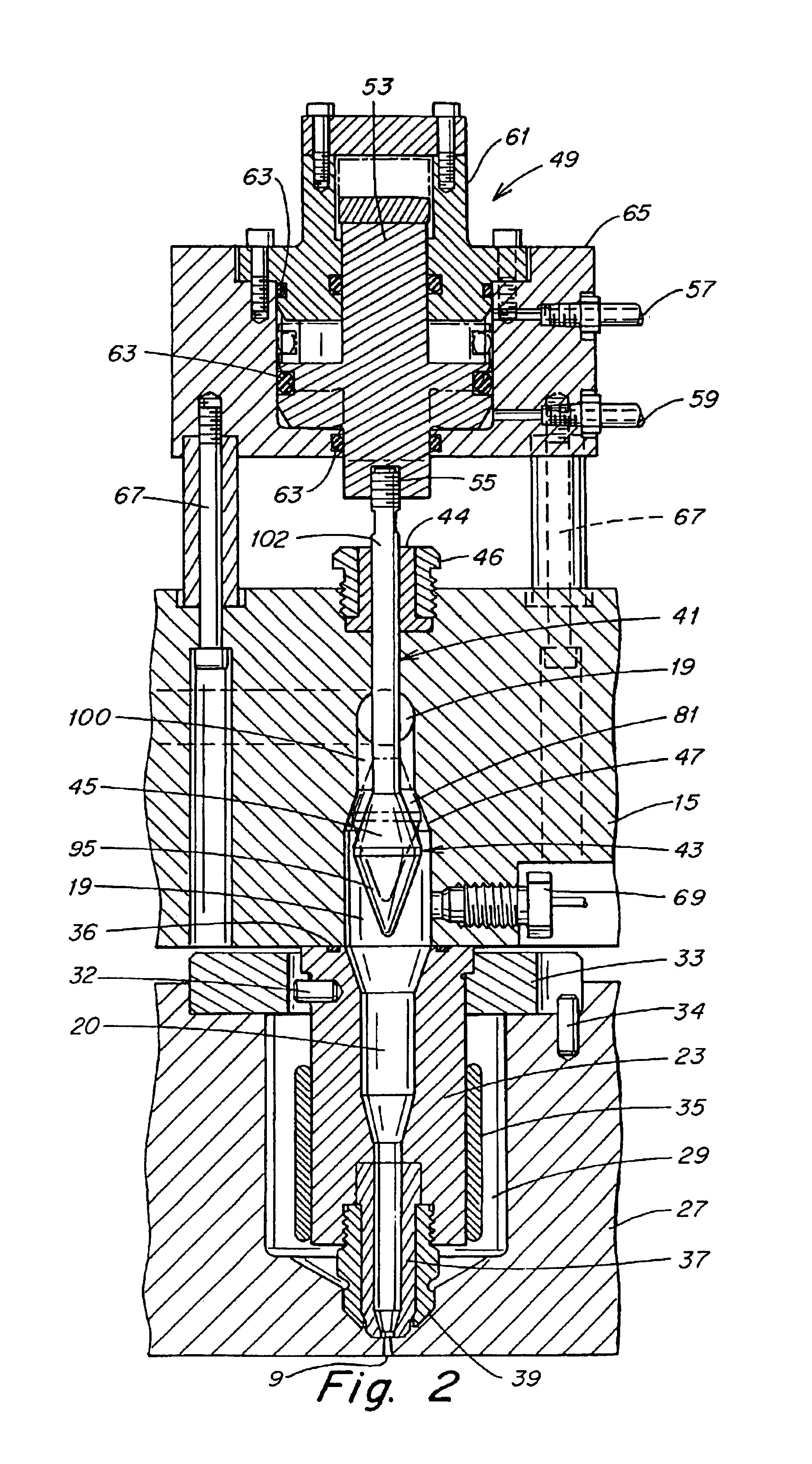
Another advantage of controlling the melt flow away from the gate is the use of a larger valve pin head 43 than would be used if the valve pin closed at the gate. A larger valve pin head can be used because it is disposed in the manifold in which the melt flow bore 19 can be made larger to accommodate the larger valve pin head. It is generally undesirable to accommodate a large size valve pin head in the gate area within the end of the nozzle 23, tip 39 and insert 37. This is because the increased size of the nozzle, tip and insert in the gate area could interfere with the construction of the mold, for example, the placement of water lines within the mold which are preferably located close to the gate. Thus, a larger valve pin head can be accommodated away from the gate.
The use of a larger valve pin head enables the use of a larger surface 45 on the valve pin head and a larger surface 47 on the bore to form the control gap 81. The more "control" surface (45 and 47) and the longer the "control" gap (81)--the more precise control of the melt flow rate and pressure can be obtained because the rate of change of melt flow per movement of the valve pin is less. In FIGS. 1-3 the size of the gap and the rate of melt flow is adjusted by adjusting the width of the gap, however, adjusting the size of the gap and the rate of material flow can also be accomplished by changing the length of the gap, i.e., the longer the gap the more flow is restricted. Thus, changing the size of the gap and controlling the rate of material flow can be accomplished by changing the length or width of the gap.

